Camera and Clipping Plane
CS-116A: Introduction to Computer Graphics
Instructor: Rob Bruce
Fall 2016
SLIDE 1: Camera and clipping plane
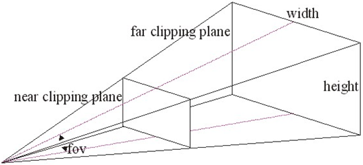
SLIDE 2: Camera and clipping plane
SLIDE 3: View from camera

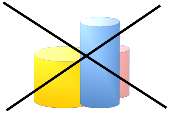
SLIDE 4: Stacking order of objects wrong!
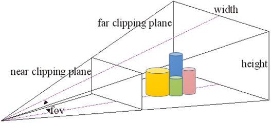
SLIDE 5: Near and far clipping planes
- Distance between near and far clipping planes: z-buffering
- Z-buffering:
- - Defines how objects stack on each other when projected onto a flat screen.
- - Objects close to near clipping plane will obstruct the view of objects in far clipping plane.
SLIDE 6: Interactive frustum program
Interactive program to adjust near and far clipping planes:
http://www.songho.ca/opengl/files/matrixModelView.zip
Note: This program will only run under Microsoft’s Windows operating system. It uses a combination of OpenGL as well as Windows API. However, you can still read the code.
The "take away" from reading the code: Linear transformations are used to adjust camera view when near or far clipping planes are adjusted. This is how we compute the view from the camera!
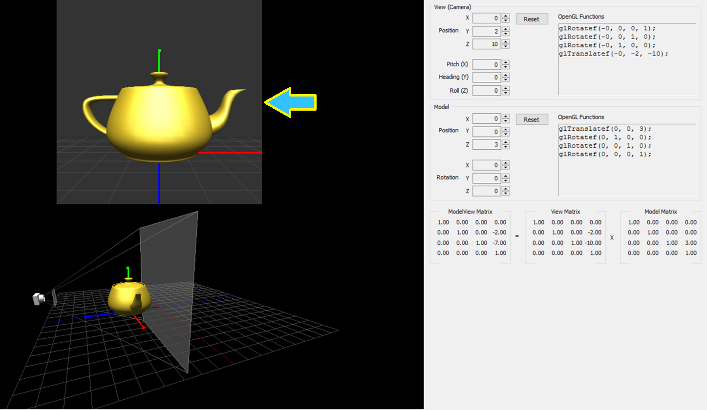
SLIDE 7: Interactive frustum program: screenshot

SLIDE 8: Interactive frustum program: screenshot
The arrow is pointing to the camera's perspective in the screenshot image below.
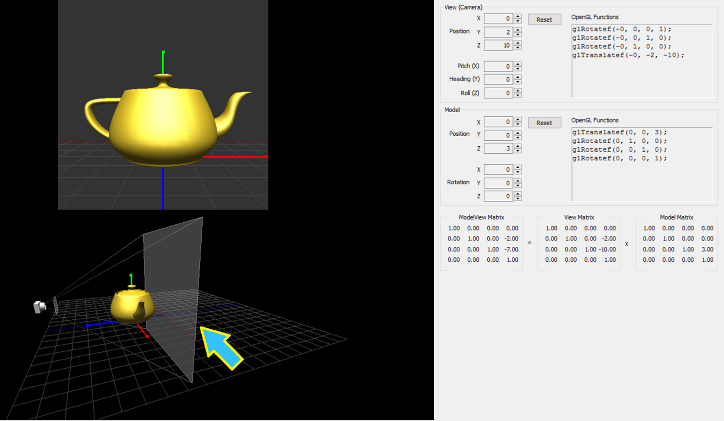
SLIDE 9: Interactive frustum program: screenshot
The arrow is pointing to the far clipping plane in the screenshot image below.
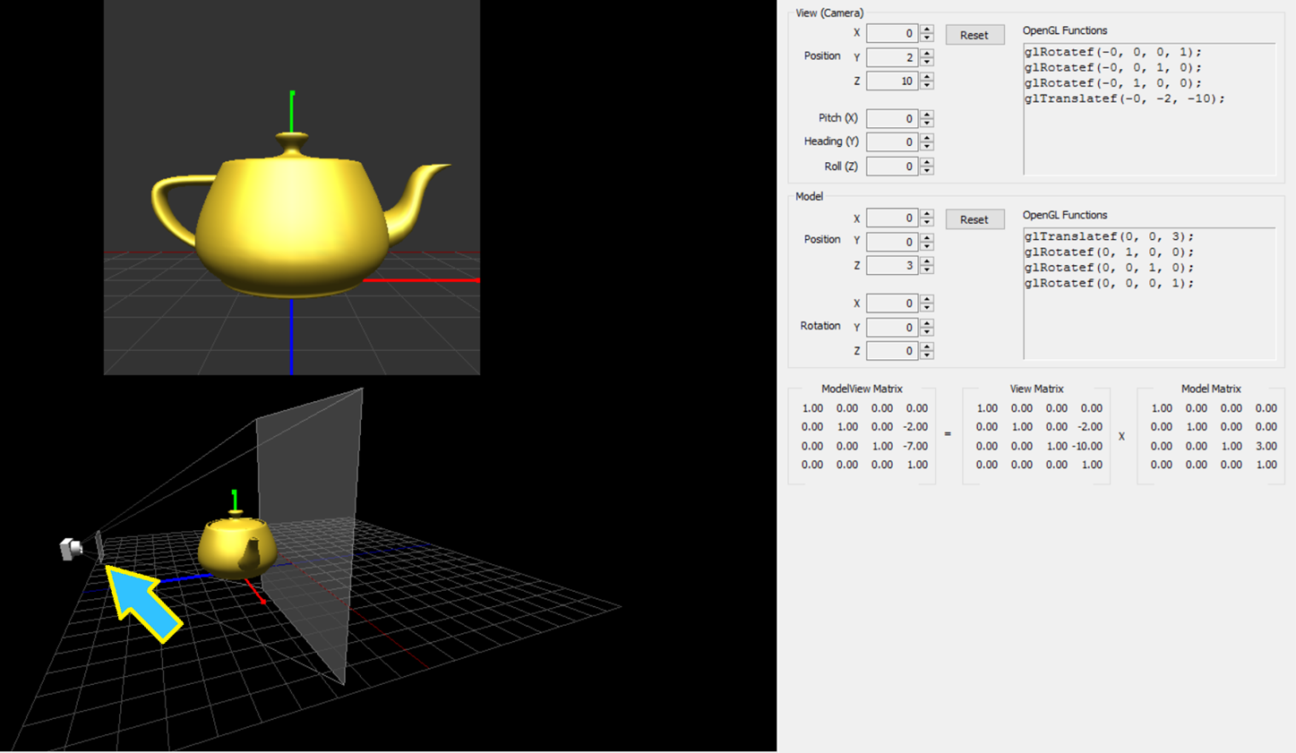
SLIDE 10: Interactive frustum program: screenshot
The arrow is pointing to the near clipping plane in the screenshot image below.
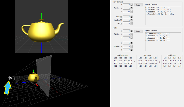
SLIDE 11: Interactive frustum program: screenshot
The arrow is pointing to the near camera in the screenshot image below.
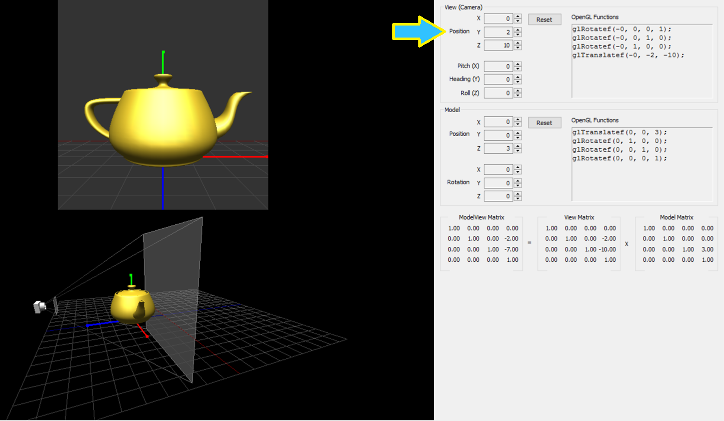
SLIDE 12: Interactive frustum program: screenshot
The arrow is pointing to a control panel to adjust the camera's position (X,Y,Z) in the screenshot image below.
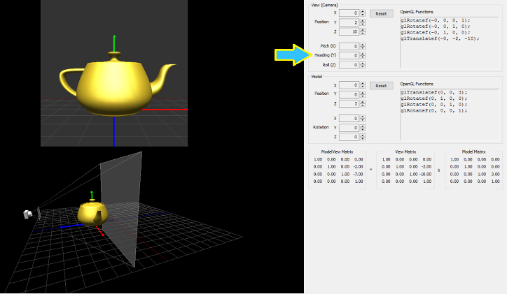
SLIDE 13: Interactive frustum program: screenshot
The arrow is pointing to a control panel to adjust the camera's rotation (yaw, pitch, roll) in the screenshot image below.
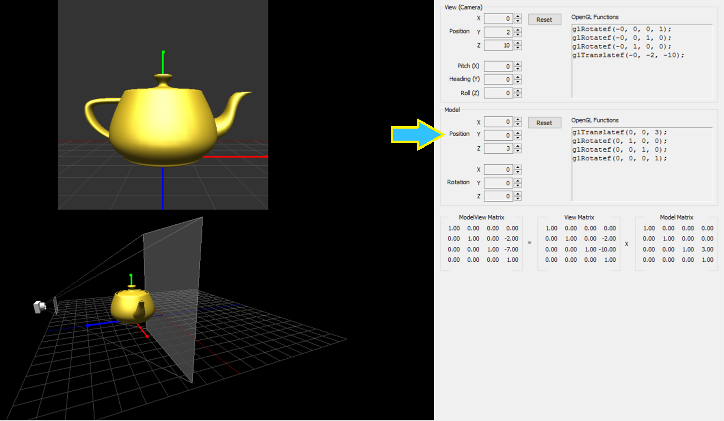
SLIDE 14: Interactive frustum program: screenshot
The arrow is pointing to a control panel to adjust the teapot's position (X,Y,Z) in the screenshot image below.
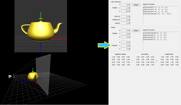
SLIDE 15: Interactive frustum program: screenshot
The arrow is pointing to a control panel to adjust the teapot's rotation (yaw, pitch, roll) in the screenshot image below.
SLIDE 16: Interactive frustum program: screenshot
The arrow is pointing to the actual OpenGL commands (i.e. what you would use in an OpenGL program) to adjust the camera's position (X,Y,Z) and rotation (yaw, pitch, roll) in the screenshot image below.

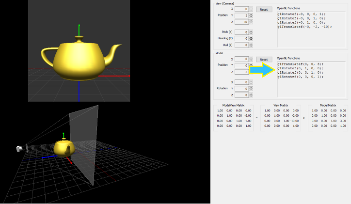
SLIDE 17: Interactive frustum program: screenshot
The arrow is pointing to the actual OpenGL commands (i.e. what you would use in an OpenGL program) to adjust the teapot's position (X,Y,Z) and rotation (yaw, pitch, roll) in the screenshot image below.
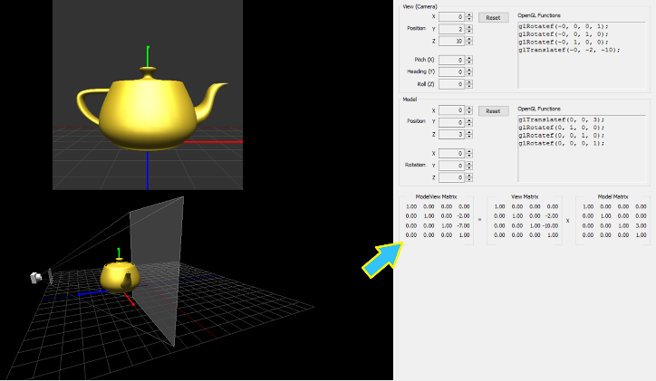
SLIDE 18: Interactive frustum program: screenshot
The arrow is pointing to the Model matrix's values that OpenGL uses to create the perspective view you see on the screen.
SLIDE 19: For further reading
Computer Graphics with OpenGL (4th Edition) by Donald Hearn, M. Pauline Baker, and Warren R. Carithers (pp. 307- 357).
Robert Bruce
Research
Courses
Fall 2016, CS-116A:
Lectures:
- Introduction to OpenGL and GLUT
- Fractals
- Splines
- Mesh: Vertices, Edges, and Faces
- Event driven programming, capturing keypresses and mouse clicks
- Camera and clipping plane
- Animating the camera
- Light and Color (part 1 of 2)
- Light and Color (part 2 of 2)
- Graphics File Formats
- Creating mouse-driven menus in GLUT
- Developing Graphical user interface widgets with OpenGL
- Hidden surface removal
- GLSL: OpenGL Shading Language (part 1 of 2)
- GLSL: OpenGL Shading Language (part 2 of 2)
- Accelerated Graphics Hardware (GPU)
- Metaballs and Blobbies
- Linear transformations
- Coordinate systems in OpenGL
- Introduction to Blender
- Algorithmic animation and modelling (part 1 of 2)
- Algorithmic animation and modelling (part 2 of 2)
- Squash, Stretch, and Bounce: The twelve principles of animation
- Character Rigging for animation
- Augmented Reality and Virtual Reality
- Introduction to WebGL
Assignments:
Handouts:
- Creating a bootable Linux Mint flash drive
- How to update software on Linux Mint
- Installing OpenGL libraries in Linux Mint
Programs:
Other
