Chris Pollett >
Students >
Chen
( Print
View )
[Bio]
[Del1]
[Del2]
[Del3]
Del 3: Simulating quantum circuit with unbounded fan-out for value gate
1 Program Description
This program performs a linear value gate calculation. Given n qubits |x> and value m, the program constructs a quantum circuit with fan-out, and then evaluates the circuit. The idea for constructing such a circuit can be found in [S02].
2 Quantum Computation
Quantum mechanics is a mathematical framework for the development of physical theories. In this section, we will review some important concepts of quantum mechanics, for details, see the textbook of quantum computation [NC00].
-
Models of quantum computation
In classical complexity theory, the concept of universal computer can be represented by several equivalent models. As for quantum computation, each of these classical concepts has a quantum counterpart, as shown in Table 1.
Model Classical Quantum Mathematical
Machine
CircuitPartial recursive function
Turing machine
Logical circuitUnitary operators
Quantum Turing machine
Quantum circuitTable 1 Classical and quantum computation models
State space
Associated to any isolated physical system is a complex vector space with inner product (that is, a Hilbert space), known as the state space of the system. The system is completely described by its state vector, which is a unit vector in the systemĂs state space.
A qubit is a two-dimensional state space. Suppose |0> and |1> form an orthonormal basis for that state space. Then an arbitrary state vector in the state space can be written as:
|ψ> = a|0> + b|1>
where a and b are complex numbers, and |a|2 + |b|2 = 1.
-
Evolution
The evolution of a closed quantum system is described by a unitary transformation. That is, the state |ψ> of the system at time t1 is related to the state |ψĂ> of the system at time t2 by a unitary operator U which depends only on the times t1 and t2,
|ψ'> = U|ψ>
An example of unitary operator is the Hadamard gate, which we denote as H. This has the action H|0> = (|0> + |1>)/√2, H|1> = (|0> - |1>)/√2, and corresponding matrix representation

-
Quantum measurement
Quantum measurements are described by a collection of {Mm} measurement operators. These are operators acting on the state space of the system being measured. The index m refers to the measurement outcomes that may occur in the experiment. If the state of the quantum system is |ψ> immediately before the measurement, then the probability that result m occurs is given by
p(m) = <ψ|Mm† Mm|ψ>
and the state of the system after the measurement is
Mm|ψ> ------------------- √ψ<ψ|Mm†Mm|ψ> The measurement operators satisfy the completeness equation
ΣmMm†Mm = I
-
Composite systems
The state space of a composite physical system is the tensor product of the state spaces of the component physical systems. Moreover, if we have systems numbered 1 through n, and system number i is prepared in the state |ψi>, then the joint state of the total system is
|ψ1> ⊗ |ψ2> ⊗ ... ⊗ |ψn>.
3 Algorithms for Simulation
In this section, we will briefly review the main results of the basic algorithm, which is used to construct the circuit implemented in this program, for details, see [S02]. In forthcoming circuits, we will need the following tools: quantum fan-out operation, parallelization method, quantum Hadamard transform, and increment operation.
3.1 Quantum fan-out operation
Notice that because of the no-cloning theorem, quantum circuits cannot contain a naive quantum counterpart of the classical fan-out operation performing
|s>|0>⊗ n --> |s>⊗ n+1 (3.1)
for a general superposition state |s>. However, a modified quantum fan-out operation can be defined. It performs exactly (3.1) for each computational basis state and the effect on superposition states is determined by linearity. The quantum fan-out operation can also be regarded as a sequence of controlled NOT operations sharing the source qubit. Define a quantum fan-out operation on source qubit |s> and n target qubits |tk> performs
|s>⊗k=1n|tk> --> |s>⊗k=1n|tk ⊕ s>
3.2 Parallelization method
Having the above quantum fan-out operator, now we are able to perform a more general task: an arbitrary number of (possibly controlled) commuting operations operating on the same qubits can be performed at the same time in the model of quantum circuits with unbounded fan-out.
First, if some operators commute, then they are all diagonal in the same basis. Second, a diagonal unitary operator consists just of phase shifts, because every coefficient in the diagonal is a complex unit. Furthermore, applying multiple phase shifts on an individual qubit can be parallelized as following:
- Apply the fan-out operation on a qubit to copy the state.
- Apply each phase shift on a distinct ˘copy÷.
- Apply the fan-out operation again, and clear the ancilla qubits.
This method can be readily generalized from one qubit to a set of qubits by copying all target qubits using the fan-out operation after basis change. Other tricks are similar to one qubit case.
3.3 Quantum Hadamard transform
Quantum Fourier Transform (QFT) is one of the main tools of quantum computing. It is a quantum equivalent of the classical Fourier Transform, but it operates on quantum amplitudes of superposition states instead of an array of numbers. For detail about QFT, see [NC00]. The main trick used in this algorithm is replacing QFT by Hadamard transform.
The Hadamard transform Hn on n qubits is the following operator (written in the computational basis):
Hn = 1/2n/2 ⊗j=02n-1|y> ⊗j=02n-1(-1)y*x<x|,
where y*x is the bitwise scalar product. A useful property of the Hadamard transform is Hn = H⊗n.
3.4 Increment operation
An increment operator P on n qubits is an operator mapping each computational basis state |x> to |x+1 mod 2n>. P is diagonal in the Fourier basis and, in this basis, can be implemented exactly by a depth 1 quantum circuit.
Define operator D = FPF†, that is the increment in Fourier basis. Define a rotation operator about the z-axis by angle θ by Rz(θ) = |0><0| + eiθ|1><1|. Then for every k ∈ {1, 2, ..., n}, Dk = Rz(π / 2n-k)⊗ Dk-1. The 0-qubit operator D0 is considered to be 1.
3.5 Value gate
Having all these tools, a circuit for value gate with unbounded fan-out can be constructed as shown in Figure 1.
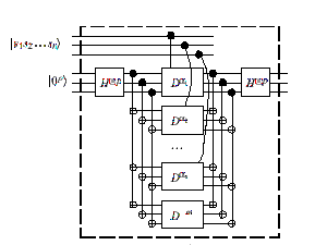
Figure 1 A circuit for value gate
4 Design and Implementation
One of the most challenging parts in implementing this algorithm is to understand substantial mathematics involved in the algorithm and quantum computation. It took me a long time to figure out the matrix for each quantum gate involved in this circuit.
4.1 Matrix design
From an implementation view, four types of layers are included in Figure 1: Permutation layer, Hadamard layer, Fan-out layer, and Increment layer. According to this consideration, from left to right, we first apply Hadamard layer to change the basis of the input vector. Then we apply permutation layer to change the order of input line. Then, apply fan-out layer, after this, we apply permutation layer again to change the order back, and apply another permutation layer to give an order that needed by applying increment layer. Then, by applying controlled increment layer on Hadamard basis, we can calculate if the number of inputs that is on is equal to a value m. We again applying permutation, fan-out, permutation, and Hadamard layer respectively to change the vector back to computational basis and eliminate ancilla qubits.
Each layer can be represented as a matrix. This matrix comes from the tensor-product of sub-matrices. The entire circuit can also be represented as a matrix, which is the product of all layers. A matrix representation for the Hadamard layer (we call it H_layer) is straightforward. H_layer = I1 ⊗ ... ⊗ In ⊗ H⊗ (n+1)*p. Next we will explain matrix representation for other layers.
-
Matrix representation for permutation operator
Give n inputs in order x, we may need to change order x to order y,
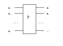
Figure 2 Permutation operator
Figure 2 illustrates a permutation. Input vector is x = (a1,a2,..., an), after permutation operation, the output is a permutation of (a1,a2,..., an), as y = (a5,a1,...,a7) shown above.
Permutation is implemented using matrix. The above diagram can be implemented with the following matrix operation:
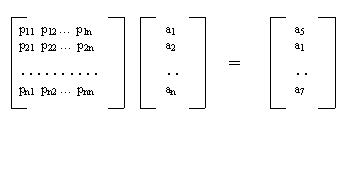
Figure 3 Matrix representation for permutation operator
For each element ai in vector x = (a1,a2,..., an), it is permuted to the output element aj in y = ( a5,a1,...,a7) which y is a permutation of x. The matrix has the following property:
- p(aj, ai) = 1 for 1<=i,j<=n
- p(i,j) = 0, otherwise
Matrix representation for fan-out operator
A matrix representation for fan-out gate of n target bits is illustrated in Figure 4. Define m = 2n+1. The size of this matrix is m x m. For the first m/2 rows, p(i, j) = 1 if i = j. For the rest rows with row number k, p(i, j) = 1 if j = m/2+m-1-i. Otherwise p(i, j) = 0.
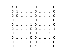
Figure 4 Matrix representation of fan-out operator
-
Matrix representation for controlled-increment operator
We consider a general case, that is, a controlled-U operator. In our implementation, we can limit our considerations to one controlled bit and n target bits. In this case, we can have a matrix representation for it, as shown in Figure 5.
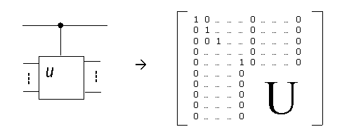
Figure 5 Controlled-U operator and its matrix representation
In this matrix, we have 2n+1 rows and 2n+1 columns. The sub-matrix that is made from the first 2n+1/2 rows by the first 2n+1/2 columns is a identity matrix. To implement a controlled-increment operator on n target bits, we can replace U by a matrix for increment, as described in Section 3.4.
4.2 Program organization
In implementation, we designed four classes: Complex number class, Matrix class, Gate class and Value gate class. In Complex number class, we define complex number and its operations. In Matrix class, we define matrix and matrix operations, such as addition, multiplication, transpose, tensor-product, and Hermitian-conjugate. In Gate class, we define a base gate, and set matrix for identity gate, Hadamard gate, fan-out gate, flip(permutation) gate, and controlled increment gate. Finally, in Value gate class, we set up quantum circuit for value gate and evaluate the circuit to output result. Figure 6 shows a class organization.
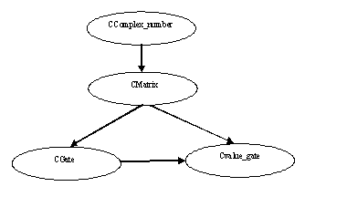
Figure 6 Class diagram
5 Test
We tested on one qubit case. According to the algorithm, if the value gate is satisfied, that is, number of inputs that is on equal to the value m, then the register, say |Z> is in computational basis state |0>. Otherwise, register |Z> is in a general superposition state. By doing a measurement <Z|Z>, we get a output value, we then negate this value to output the result. Table 1 shows test result on one qubit case. In this table, we see that if value gate is satisfied, program output 1, otherwise 0.
| Input qubit | Value m | Output |
| 0> | 0 | 1 |
| 0> | 1 | 0 |
| 1> | 0 | 0 |
| 1> | 1 | 1 |
Table 1 Test result on one qubit case
6 Limitation of the Implementation
Currently, our program is an initial implementation. For now, both space complexity and time complexity are high. Give n qubits, the space and the time complexity for this implementation is O(2nlog(n)). So far, we know that this algorithm is in PSPACE, because BQP lies somewhere between P and PSPACE [NC00], see Figure 7.
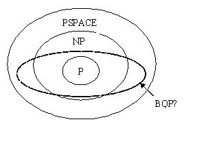
|
| Figure 7 The relationship between classical and quantum complexity classes |
Because of the exponential complexity of our current implementation, we are not able to evaluate large number of qubits. However, it does give us the insight of how the quantum algorithm works. Currently, we are actively exploring ways of reducing both space and time complexity and are making good progress.
Reference:
[S02] R. Spalek. Quantum Circuits with Unbounded Fan-out. Submited to STACS 2003 v2.
[NC00] Quantum Computation and Quantum Information. M.Nielson and I.Chuang. Cambridge. 2000.