Last Wednesday, we began talking about geometric models which might be used in VR Scenes.
We want to learn a little about the underlying concepts of computer graphics needed for a deeper
understanding of Virtual Reality.
We talked about how such models are typically built out of triangle meshes.
Here a triangle might be specified as a triple of triples:
`((x_1, y_1, z_1)`,`(x_2, y_2, z_2)`,`(x_3, y_3, z_3))`
We then asked several questions about mesh manipulation. For example, how do we specify how
triangles look? How do we make objects move? Etc.
We started talking about a slide related to the half-edge data structure often used in meshes, but did not complete it.
So that's where I'd like to start today...
Data Structures
Suppose we want to represent some model in memory.
One starting point would be just to use an array of triangle vertices.
Many vertices might be shared across triangles, so if we list them multiple times, we are wasting space.
To solve this, one could imagine having an array of vertices and an array of triangles. Now, though, each triangle rather than consisting of three subarrays of triples, consists instead of three integers consisting of the index in the vertex array.
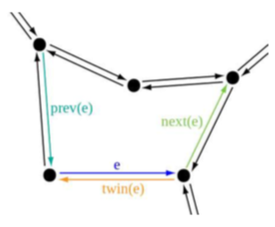
A slightly more complicated data structure which enables us to answer many of the questions of meshes from last day is the doubly connected edge list, also known as a half-edge structure.
It consists of three data elements, faces (in our case, these will be triangles), edges, and vertices.
Each edge represents the border of one or two triangles, without duplicates.
The data structure contains points (see figure above) between adjacent faces, edges, and vertices, so that algorithms can quickly traverse the model components in a way that corresponds to how they are connected together.
In this structure, each edge has two pointers, a next and a previous, each of which belongs to two different faces.
Faces are made up of half-edges which have be traversed from one to the other in a cycle, giving an orientation and hence an inside or outside to the face.
Other structures besides the half-edge data structure, are used to manipulate/answer similar questions about meshes. One example is the wing-edged data structure.
Aspects of Models
Inside Versus Outside
If we have a mesh in which every triangle shares an edge with exactly one other triangle and where no triangles intersect unless they are adjacent (by sharing an edge), then the model will have a well defined inside and outside volume, and we have coherent model.
At the other extreme, we have random triangles in space, a polygon soup.
Tools like Blender and Maya can be used to make a coherent models.
Triangle Use. Triangles are typically used rather than more complicated surface primitives such as quadrilaterals, splines and semi-algebraic surface because they are simpler and a lot of hardware (GPUs) is optimized toward triangle algorithms.
Stationary Versus Movable
Stationary models are models which keep their coordinates forever. For example, streets, floors, and buildings.
Movable models are models which can be transformed into various positions and orientations. For example, vehicles, avatars, etc.
A model might move to match the user's motion, in response to controls such as gamepads, or in response to world physics.
Coordinate Axes. We often want to match coordinates in the virtual world to things that make sense to use in the real world. For example, `(1,0,0)` in the virtual world should roughly be 1 meter to the right of `(0,0,0)`. The points `(0,0,0)` in the virtual world should make sense. I.e., y=0 intuitively corresponds to ground-level, or sea level.
Viewing Location. To determine how models in our VR scene will look when displayed, we need to:
Determine where the points in the virtual world should appear on the display by combining viewing and other transformations.
Determine how the model should appear after taking into account lighting and surface properties.
Together these two tasks are the rendering problem.
Rigid Body Transformations
We next look at the kinds of transformations of a model needed to place it in a scene.
These include: translations, rotations, and scaling.
Changing Position
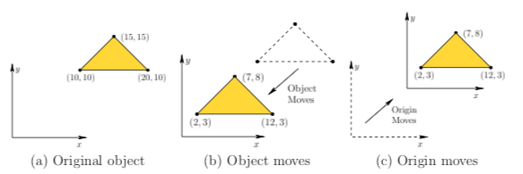
Consider the following problem: We have a model of a person centered at the origin and we now want to position the person within our VR scene at some location `(x_t, y_t, z_t)`.
For each triangle,
`((x_1, y_1, z_1)`,`(x_2, y_2, z_2)`,`(x_3, y_3, z_3))`,
in our model, one way to accomplish this would be to apply a translation:
`(x_1, y_1, z_1) mapsto (x_1 + x_t, y_1 + y_t, z_1 + z_t)`
`(x_2, y_2, z_2) mapsto (x_2 + x_t, y_2 + y_t, z_2 + z_t)`
`(x_3, y_3, z_3) mapsto (x_3 + x_t, y_3 + y_t, z_3 + z_t)`
Notice we only have to apply an operation to each of the vertices in our mesh data structure, we don't have to change which points belong to which edge, etc.
After the transformation the size and the shape of the figure will be unchanged, only its position will be changed.
Relativity
When applying a translation, it can often be interpreteted in two different ways.
For example, in the above figure, one can interpret the translation `x_t = -8`, `y_t = -7` as:
The object moving by `(-8,-7)`.
The origin of the world moving by `(8,7)`.
The idea of relativity is that we can't really tell these two situations apart.
We have to worry about this because it can be a source of VR sickness.
Quiz
Which of the following statements is true?
A CAVE is an example of a user-fixed display.
We said MEMS might be used to solve the vergence-accomodation mismatch problem.
Steven's power law is the relationship `p= cm^x`.
Changing Orientation 2D
To make the wheels in a car turn, to change where we are looking at, to turn an object over, etc., we often need to change the orientation in a virtual world.
The operation that changes the orientation is called a rotation.
We first look at the 2D case.
Recall a point `(x,y)` in 2D can be viewed as complex number `x + iy` where `i := sqrt(-1)`.
We can write this point `(x,y)` as `re^{i theta}` (Euler's Formula) where `r = sqrt(x^2 +y^2)` and `theta = 2arctan(y/(r+x))`.
We recall `e^{i theta} = cos theta + i sin theta` as can be verified by the Taylor series for `e^x`, `sin x` and `cos x`.
If we want to rotate a point about the origin by `phi`, we can thus multiply `re^{i theta}` by `e^{i phi}` to get `re^{i (theta + phi)}`.
In terms of `x` and `iy`, under this operation `x` becomes `x cos phi + ix sin phi` and `iy` becomes `iycos phi - ysin phi = - y sin phi + iycos phi`.
Suppose we want to express this rotation in terms of a 2x2 matrix: `((m_{11}, m_{12}),(m_{21}, m_{22}))`.
If we write `x+iy` as a column vector `((x), (y))` and group the real and imaginary parts of the above, then we want to solve the equation:
`((m_{11}, m_{12}),(m_{21}, m_{22}))((x), (y)) = ((x cos phi - y sin phi), (ycos phi + x sin phi))`.
We thus get a counter-clockwise rotation bt `phi` about the origin is given by the matrix:
`((cos phi, -sin phi),(sin phi, cos phi))`.
Changing Orientation 3D
The book identifies three properties of a `2x2` matrix or `3x3` matrix that are necessary and sufficient for it to be a rotation:
It must preserve length, so the euclidean length of each of the columns must be 1. For a `2x2` matrix, `((m_{11}, m_{12}),(m_{21}, m_{22}))` this would mean that `m_{11}^2 + m_{21}^2 = 1` and `m_{12}^2 + m_{22}^2 = 1`.
There is no sheering in one axis over another. To prevent this the inner product of each of the columns must be 0.
It is not a reflection. To check this, one can compute its determinant and see if it is 1. I.e., `det((m_{11}, m_{12}),(m_{21}, m_{22})) = m_{11}m_{22} - m_{12}m_{21} = 1`.
Yaw, Pitch, and Roll
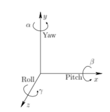
It turns out in 3D an arbitrary matrix satisfying these three conditions and can be computed as product of three 2D rotations
`R(alpha, beta, gamma) = R_y(alpha)R_x(beta)R_z(gamma)`
about each of the `x,y,z` axes indicated in the figure above.
Here roll is a counterclockwise rotation about the `z`-axis and has equation:
`R_z(gamma) = ((cos gamma, -sin gamma, 0),(sin gamma, cos gamma, 0),(0, 0, 1))`
Here pitch is a counterclockwise rotation about the `x`-axis and is given by the equation:
`R_x(beta) = ((1, 0, 0), (0, cos beta, -sin beta),(0, sin beta, cos beta))`
Here yaw is a counterclockwise rotation about the `y`-axis and is given by the equation:
`R_y(alpha) = ( (cos alpha, 0, -sin alpha),(0, 1, 0),(sin alpha, 0, cos alpha))`
Be careful! Rotations are not commutative a yaw of `pi/2` followed by a pitch of `pi/2` is not the same as a
pitch of `pi/2` followed by a yaw of `pi/2`.
Not realizing this can cause problems when constructing VR scenes.
Matrix Multiplications are Backwards
Suppose we want to rotate a point `p= (x,y,z)`.
We have two rotation matrices `R` and `Q`.
If we rotate `p` using `R`, we get `p' = Rp`.
If we then rotate by `Q`, we have `p'' = Qp'`.
Suppose we want to matrix multiply the two rotations to get a single operation to go from `p` to `p''`.
Often, programmers are tempted to compute `RQ`, rather than the `QR` we actually did: `(QR)p = Q(Rp) = Qp' = p''`.
Matrices Multiplication for Translations and Rotations
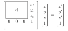
Currently, we can apply a rotation `R` followed by a translation
via the equation:
`((x'), (y'), (z')) = R((x),(y), (z)) + ((x_t), (y_t), (z_t))`
If we go to 4x4 matrices, we can actually do this with one matrix multiply:
Denote the matrix above `T_{rb}`. It is called the homogeneous transformation matrix.
The rb is used to indicate the matrix is a rigid body transform. I.e., It does not distort objects.