The Micro-1 Processor
Here's the organization of a computer equipped with a Micro-1 processor:
Memory contains an array of integer cells:
int cell[] = new int[CAP];
where CAP is the capacity of memory. Initially this is set to 256.
Internally, the Micro-1 processor is equipped with eight 32-bit data/address registers and two 32 bit control registers:
PC, the program counter, contains the address of the next instruction to execute.
IR, the instruction register, contains the hexadecimal representation of the current instruction being executed.
Here's a sketch of the Micro-1 fetch-execute cycle:
1. IR = cell[PC++]
2. if (IR == 0) halt
3. execute IR
4. goto 1
Micro-1 Data Types
The only Micro-1 data type is int, 32-bit integers. False is represented by 0 and true is represented by any non-zero integer.
Micro-1 Instruction Set
Micro-1 Assembly Language
Assume a and b are register indices. This means 0 <= a, b < 8.
Data Control
1. load a b // reg[a] = cell[reg[b]]
2. loadc a // reg[a] = cell[PC++]
3. store a b // cell[reg[a]] = reg[b]
Arithmetic
4. add a b // reg[a] = reg[a] + reg[b]
5. mul a b // reg[a] = reg[a] * reg[b]
6. sub a b // reg[a] = reg[a] - reg[b]
7. div a b // reg[a] = reg[a] / reg[b], error if reg[b] == 0
Logic
8. and a b // if (reg[a] != 0 && reg[b] != 0) reg[a] = 1 else reg[a] = 0
9. or a b // if (reg[a] != 0 || reg[b] != 0) reg[a] = 1 else reg[a] = 0
10. not a b // if (reg[b] != 0) reg[a] = 0 else reg[a] = 1
Bitwise
11. lshift a b // reg[a] = reg[b] << 1
12. rshift a b // reg[a] = reg[b] >> 1
13. bwc a b // reg[a] = reg[a] & reg[b]
14. bwd a b // reg[a] = reg[a] | reg[b]
// 14. comp a b // reg[a] = ~reg[b]
Sequence Control
15. if a b // if (reg[a] != 0) pc = reg[b]
0. halt // stop fetch-execute cycle
Micro-1 Machine Language
Micro-1 machine language instructions are just the hexadecimal representation of Micro-1 assembly language instructions.
The number of each instruction shown above is its opcode, p, where 0 <= p < 16.
The format of a Micro-1 machine language instructions is the hexadecimal number:
0x00000pab
Where
p = the 4-bit opcode
a = argument 1 = the 4 bit index of some register
b = argument 2 = the 4 bit index of some register
Sample Program 1
The following program implements:
cell[23] = cell[20] + cell[21] + cell[22]
We begin by loading constants into the first three registers:
loadc 0
0x14
loadc 1
0x0
loadc 2
0x1
Register 0 will be our address register. It holds address 20 (0x14), where our first summand is stored.
Register 1 will be our accumulator. This is where the sum will be stored. Initially it holds 0.
Register 2 holds the constant 1, which will be repeatedly added to the address.
Here are the hexadecimal representations of these instructions:
0x00000200 // loadc 0
0x00000014 //
0x14 = 20 -> reg[0] = 20
0x00000210 //
loadc 1
0x00000000 //
0 -> reg[1] = 0
0x00000220 //
loadc 2
0x00000001 // 1
Register 3 will hold the next number to add to the accumulator.
load 3 0 // reg[3] = cell[reg[0]] = cell[20]
Now we add register 3 to the accumulator, then increment the address register:
add 1 3 // reg[1] +=
reg[3]
add 0 2 // reg[0] += reg[2]
Here's the hexadecimal for these three instructions:
0x00000130 // load 3 0 -> reg[3] = reg[0]
0x00000413 // add 1 3 -> reg[1] += reg[3]
0x00000402 // add 0 2 -> reg[0] += reg[2]
We repeat these three instructions two more times:
load 3 0 // reg[3] = cell[reg[0]] = cell[21]
add 1 3 // reg[1] += reg[3]
add 0 2 // reg[0] += reg[2]
load 3 0 // reg[3] = cell[reg[0]] = cell[22]
add 1 3 // reg[1] += reg[3]
add 0 2 // reg[0] += reg[2]
Now we are ready to write the accumulator back to memory location 23, then halt:
store 0 1 // cell[reg[0]]
= reg[1]
halt
Here's the hexadecimal:
0x00000301 // store 0 2 ->
mem[reg[0]] = reg[1]
0x00000000 // halt
Here's a test harness
To test this program we make the following assignments:
cell[20] = 100
cell[21] = 200
cell[22] = 300
The entire program can be found in program1.m1.
Here's a snapshot just before halt is executed:
-> registers
Registers:
reg[0] = 17
reg[1] = 258
reg[2] = 1
reg[3] = 12c
reg[4] = 0
reg[5] = 0
reg[6] = 0
reg[7] = 0
PC = 10
IR = 301
-> memory
cell[0] = 200
cell[1] = 14
cell[2] = 210
cell[3] = 0
cell[4] = 220
cell[5] = 1
cell[6] = 130
cell[7] = 413
cell[8] = 402
cell[9] = 130
cell[a] = 413
cell[b] = 402
cell[c] = 130
cell[d] = 413
cell[e] = 402
cell[f] = 301
cell[10] = 0
cell[11] = 0
cell[12] = 0
cell[13] = 0
cell[14] = 64
cell[15] = c8
cell[16] = 12c
cell[17] = 258
etc.
Note that all values are in hexadecimal (base 16), so
cell[17] = 258
translates in decimal to:
cell[23] = 600
Project
Create and test a simulator for a computer equipped with a Micro-1 processor.
Design
The Micro-1 simulator consists of three classes:
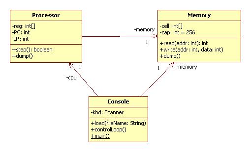
Recall that in a UML class diagram arrows and attributes translate into fields.
Warning: additional fields and methods may be needed.
Hints
Console.java has been implemented for you, including a javadoc page.
To get started, determine which methods Memory and Processor need. This can be determined from studying Console.java and the UML class diagram. Quickly create Memory and Processor classes with these methods. Don't worry about how the methods should work. The only important thing is that the program compiles and runs. Next, replace the implementation of the Memory methods with ones that work. This should be easy, but may involve adding fields to the class. Then replace the implementation of the Processor methods with ones that work. This may also involve adding fields to the Processor class. Finally, test your program on program1.m1.
Processor.java will need to make use of Java's right shift (>>) and bitwise conjunction (&) to mask out and shift fields of IR representing opcodes and arguments.
Testing
Test your implementation by writing and running the following Micro-1 programs:
1. cell[103] = 3 * cell[100] + 2 * cell[101] + cell[102]
2. cell[101] = 2cell[100] // hint: use left shift
3. cell[101] = cell[100] + cell[100] – 1 + cell[100] – 2 + ... + 1
Note: these numbers are in base 10.
Extra Credit
Add an assembler
Modify the load method in the Console class so that it reads a file containing Micro-1 assembly language instructions instead of hexadecimal machine language instructions.
The translation should be easy. For example:
add a b translates into the hexadecimal number 4ab
Interpret everything in the file after the halt instruction as a hexadecimal constant.
Add a GUI
Replace Console.java with Micro1Viewer.java. The viewer contains a control panel (JPanel) with text fields (JTextField) showing the current content of each register, and buttons (JButton) for the Console commands: step, load, memory (dumps to the command console), and registers (updates the text fields.)
See my JFC Notes for information on how to build GUIs using Java and Swing.