4
Graphics
Programming 1.0
4.1
Overview
The chapter begins with a brief description of device contexts and an introduction to the basic graphics support types: Point, Rectangle, and Size. Following this, the basic ideas of graphics programming in MFC are presented with three simple examples. The first example, Screen Test 1.0, demonstrates the often unappreciated difference between three important rectangles: the screen, the view window, and the device context's canvas. The second example, Paint 1.0, introduces bitmaps and demonstrates setting pixels to arbitrary colors.
The third example, Draw 1.0, allows users to drag an ellipse using the mouse. Unlike the Paint program, the ellipse has mathematical properties that distinguish it from the set of colored pixels users see on the screen. Because the ellipse is a mathematical abstraction, users can alter its color and shape dynamically.
Specifying the new color and shape of an ellipse presents a user interface problem: the view window is being used to display graphics, where can the necessary input controls such as sliders, edit boxes, and buttons be placed? To solve this problem the chapter introduces readers to modal and modeless dialog boxes.
Chapter 5 presents second versions of these three applications.
4.1.1 Chapter Prerequisites
4.2
OnDraw()
Every view inherits a protected pointer to its document from the CView base class. In addition, every view inherits a do-nothing OnUpdate() function, which it can redefine. As we learned in the previous chapter, this function is indirectly called by the document each time the application data changes. Each view also inherits a virtual function called OnDraw():
class CView : public CWnd
{
public:
virtual void OnUpdate(...) {}
virtual void OnDraw(CDC* pDC) = 0;
protected:
CDocument* m_pDocument;
// etc.
};
The "= 0" that follows the declaration of OnDraw() indicates that it is a pure virtual function. A pure virtual function has no implementation in the base class and therefore must be redefined by derived classes.
What is OnDraw() supposed to do? OnDraw() draws the application data in the view window. The operating system indirectly calls OnDraw() every time the window is resized or uncovered. The application can also arrange to have OnDraw() called every time the document is modified.
Until now we have chosen CFormView as the base class of our view classes. We didn't need to implement OnDraw() because CFormView provided an implementation for us, namely:
void CFormView::OnDraw(CDC* pDC)
{
for each control, c, on this form:
c.OnDraw(pDC);
}
In this chapter we will use CView as the base class of our views. This means the burden of implementing OnDraw() will fall on our shoulders.
4.3
Device
Contexts
Each time OnDraw() is called, it is passed a pointer to a CDC object. CDC is the base class of all Windows device context classes. A device context is a virtual graphics device. It provides a blank canvas with a coordinate system, drawing tools (pen, brush, font, and palette), and a collection of member functions for changing the tools and using the tools to draw points, lines, curves, and shapes:
class CDC : public CObject
{
public:
HDC m_hDC; // handle to system-level DC
// drawing functions:
CPoint MoveTo(int x, int y);
BOOL LineTo(int x, int y);
BOOL Ellipse(int x1, int y1, int x2,
int y2);
BOOL Rectangle(int x1, int y1, int x2,
int y2);
BOOL TextOut(int x, int y, LPCTSTR
lpszString);
COLORREF SetPixel(int x, int y,
COLORREF crColor);
COLORREF GetPixel(int x, int y) const;
// etc.
// state functions:
int GetMapMode();
int SetMapMode(int nMapMode);
CPen* SelectObject(CPen* pPen);
CBrush* SelectObject(CBrush* pBrush);
// etc.
private: // canvas and tools:
CPen* m_currentPen;
CBrush* m_currentBrush;
CFont* m_currentFont;
CPalette* m_currentPalette
CBitmap* m_currentBitmap; // the canvas
CPoint m_currentPosition;
int m_currentMappingMode;
// etc.
};
Calling a CDC member function ultimately results in calling functions that drive a monitor, printer, or other type of graphics output device. The device context makes it possible for us to write graphics code that is independent of the type of graphics devices being used by our clients.
Each time OnDraw() is called, it is supplied with a new graphical context, complete with a set of tools and a blank canvas. OnDraw() will use the drawing tools to draw a "picture" of the document's data on the canvas.
4.4
Graphics
Support Types
Before we see some examples of graphics programs, we need to mention a few supporting types provided by the Win32 API and MFC.
4.4.1 Points and Sizes
The canvas, screen, and view window are equipped with two-dimensional integer coordinate systems. A point in one of these coordinate systems is an instance of the Point class declared in the Win32 API:
typedef struct {
long x, y;
} Point;
Notice that the Point class is declared using the reserved word struct instead of class. This means that the default visibility of its member variables, x and y, is public instead of private. Therefore, clients can access and modify x and y directly.
MFC introduces a class derived from Point called CPoint. CPoint inherits the Point member variables without adding any additional member variables. Therefore, Points and CPoints are the same size and are interchangeable in most contexts. CPoint takes advantage of C++ by adding constructors and overloaded arithmetic operators that allow clients to combine and compare points:
class CPoint: public Point
{
public:
BOOL operator==(POINT point) const;
BOOL operator!=(POINT point) const;
CPoint operator-() const;
CPoint operator+(POINT point) const;
// etc.
};
The following code fragment shows some of these functions in action. First, we declare three points, p, q, and r. The default constructor initializes r to (0, 0), while a provided constructor initializes p to (3, 4) and q to (2, 5):
CPoint p(3, 4), q(2, 5), r;
Next, we assign the sum of p and q, (5, 9), to r provided p and q are different, otherwise the negation of q, (-2, -5) will be assigned to r. Because p and q are different, their sum is assigned to r:
if (p != q)
r = p + q; // r = (5, 9)
else
r = -q; // r = (-2, -5)
The significance of the statement is that we can use overloaded operator symbols !=, +, =, and - to compare, add, assign, and negate points, respectively.
The last statement assigns the y coordinate of p, plus 1, to the x coordinate of p:
p.x = p.y + 1; // p = (5, 4)
This example shows that the x and y coordinates of a point can be accessed directly and can appear on the left or right hand side of an assignment operator.
Rectangles are an important data structure in graphics programming. For example, the screen, view, and canvas are rectangles, and the size of a shape is often given by the smallest rectangle that contains it. The Win32 API provides a rectangle class with member variables representing the x coordinates of the top and bottom as well as the y coordinates of the left and right sides:
typedef struct {
long left;
long top;
long right;
long bottom;
} Rect;
In addition, the Win32 API provides a size structure for representing the width and height of a rectangle:
typedef struct {
long cx; // width of a rectangle
long cy; // height of a rectangle
} Size;
Naturally, MFC provides derived classes that add constructors and overloaded operations to these types:
class CSize: public Size { ... };
class CRect: public Rect { ... };
In fact, MFC adds constructors and casting operators so that CSize objects can be used in contexts where CPoint objects are expected and vice-versa. In short, CPoint and CSize are interchangeable in MFC.
4.4.2 Rectangles
The basic rectangle constructor (there are others) allows programmers to specify the left, top, right, and bottom coordinates of a rectangle:
CRect r(2, 4, 5, 6);
The y-axis of screen, view, and canvas coordinates goes in the opposite direction of the y-axis of the real coordinate system. This reverses the intuitive meaning of top and bottom. The top of our rectangle is above the bottom of the rectangle on the screen, even though the y-coordinate of the top is smaller than the y-coordinate of the bottom:
The top left corner of r is the CPoint (2, 4), the bottom
right is (5, 6), the center point is
(4, 5). (Note: The center point should have been (3.5, 5), except coordinates
are always integers.) The height of r is two and width is three. CRect provides
member functions for accessing this information. The following statements use
these functions to compute the area of a rectangle and to add center and corner
points:
int area = r.Height() * r.Width();
CPoint p = r.TopLeft() + r.CenterPoint() + r.BottomRight();
Rectangles are mutable objects. This means programmers can dynamically change the size and location of a rectangle. The most direct way to do this is to use CRect::SetRect():
CRect::SetRect(int top, int left, int right, int bottom);
Here's a sample call:
r.SetRect(9, 7, 2, 4);
and here is what r looks like after the call:
Unfortunately, the modified version of r is now upside down. The top left corner is (9, 7), the bottom right corner is (2, 4), the height is negative three, and the width is negative seven! To prevent this kind of confusion, rectangles should be normalized after each modification:
r.NormalizeRect();
Although this doesn't change the image of r, the top left is now (2, 4), (9, 7) is the bottom right, the height is three, and the width is seven.
MFC provides many other ways to modify the size and position of a rectangle. For example, we can inflate a rectangle using the InflateRect() member function:
r.InflateRect(1, 2, 3, 4);
Now r has height 9 and width 11:
Similarly, the DeflateRect() function can be used to shrink r.
If we define the position of a rectangle to be the position of its top left corner, then we can move rectangles using the OffsetRect() function:
r.OffsetRect(3, 4);
Alternatively, we can use the + operator:
r = r + CPoint(3, 4);
In either case, the top left corner of r becomes (4, 6) and the bottom right corner becomes (15, 14). However, the height and width or r remain fixed.
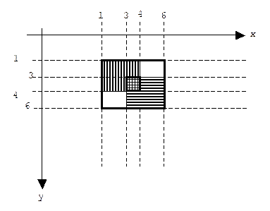
A rectangle can also be set to the union or intersection of two other rectangles. For example, assume two squares are created:
CRect r, r1(1, 1, 4, 4), r2(3, 3, 6, 6);
Here's a picture of r1 and r2:

We can set r to the intersection of r1 and r2 using the IntersectRect() member function:
r.IntersectRect(r1, r2);
Alternatively, we can use the bit-wise conjunction operator:
r = r1 & r2;
Now r is the height one, width one rectangle formed by the overlap of r1 and r2:

We can set r to the union of r1 and r2 using the UnionRect() member function:
r.UnionRect(r1, r2);
Alternatively, we can use the bit-wise disjunction operator:
r = r1 | r2;
Now r is the smallest rectangle that contains r1 and r2:
4.5
Screen
Test 1.0
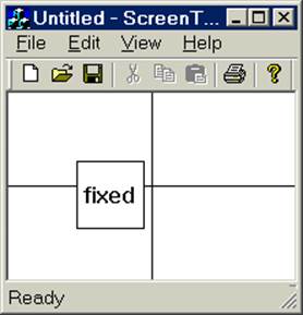
The purpose of Screen Test, our first graphics program, is to acquaint readers with the difference between the canvas and the view window as well as the automatic repaint mechanism.
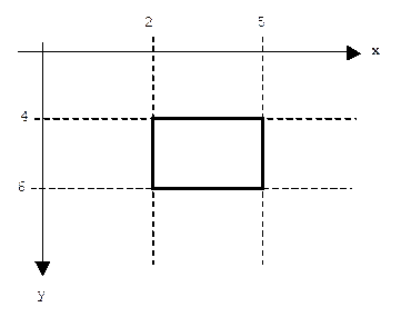
Version 1 of Screen Test displays a rectangle labeled with the text "fixed" and a pair of perpendicular lines. One line runs from the top-center of the view window to the bottom-center. The other line runs from the left-center of the view window to the right-center. The two lines cross in the center of the view window:
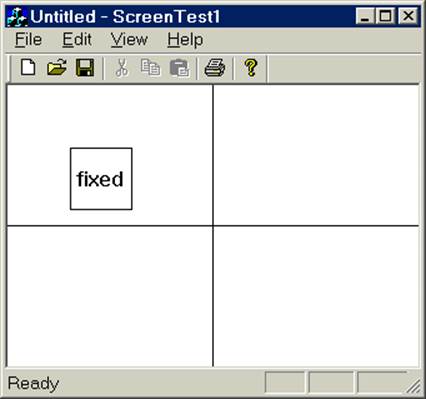
Like any window, the main window of Screen Test can be resized by dragging its borders or corners. Of course this resizes the view window circumscribed by the main window. Each time the view window is resized, the operating system automatically calls the view's OnDraw() function, passing it a new blank canvas upon which the labeled rectangle and perpendicular lines must be redrawn. After a few experiments, we notice that the labeled rectangle never seems to move relative to the view window, but that the perpendicular lines always extend from the edges of the view window and cross in the exact center.
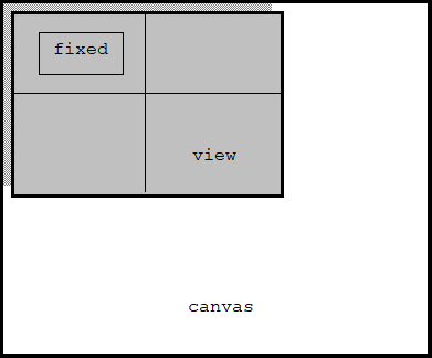
To understand this behavior it helps to realize that windows are called windows because that's what they are. Every window hovers above a canvas. By making the window larger, we see more of the underlying canvas. By scrolling, we move the window over different regions of the canvas.
Screen test places the "fixed" rectangle at a fixed point on the underlying canvas, but the placement of the center lines will depend on the size and position of the view window. For example, the view starts out with a default size and hovering over the upper left corner of the canvas:
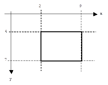
After scrolling[1] and resizing the window, it hovers over a different region of the canvas:
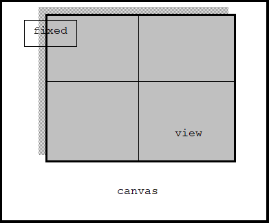
Notice that the size and position of the view window doesn't affect the fixed rectangle, but it does affect the position and length of the center lines.
4.5.1 Implementation
Screen Test is a single document application. Unlike previous examples, in the App Wizard's [Step 6 of 6] dialog box, we accept the default choice for the base class of our view: CView.
Step 1: Use the MFC App Wizard to create a single document application named ScreenTest1. Accept all of the defaults offered by the wizard.
Locate the implementation of OnDraw() in ScreenTest1View.cpp. Anticipating that this function will draw application data stored in the document, the App Wizard has helpfully declared a pointer to the document, validated the pointer, and inserted a reminder comment:
void CScreenTest1View::OnDraw(CDC* pDC)
{
CScreenTest1Doc* pDoc = GetDocument();
ASSERT_VALID(pDoc);
// TODO: add draw code for native data
here
}
Our application doesn't have any data, so we won't be needing the document pointer. Instead, we simply add code that draws the labeled rectangle and the perpendicular lines.
Step 2: Add code to CScreenTest1View's OnDraw() function that draws a labeled, fixed rectangle. Build and test the application.
Drawing a labeled rectangle is easy. Every device context has a member function which, given a pointer to a CRect as input, uses its pen to draw the rectangle on its canvas. Every device context also has several functions called TextOut() for drawing text. The version we use expects three arguments: the x and y co-ordinates of the upper-left corner of a bounding box of the text, and the text to display. (A bounding box of a shape or text is the smallest rectangle that circumscribes the shape.) In the case of text, we only need to specify the upper-left corner of the bounding box. The font size and string length will automatically determine the height and width of the bounding box.
We arbitrarily choose (50, 50) for the upper left corner of our fixed rectangle, and (100, 100) for the bottom right corner. Through trial and error we choose (55, 65) as the upper left corner for the bounding box of the text:
CRect fixed(50, 50, 100, 100);
pDC->Rectangle(&fixed);
pDC->TextOut(55, 65, "fixed");
Of course MFC provides various font metrics that allow us to calculate the exact size of the bounding box for the text. This would have allowed us to perfectly center the text in the rectangle.
Step 3: Add code to the OnDraw() function in the Screen Test 1 view that draw perpendicular lines centered in the view window. Build and test the application.
Every device context is equipped with a virtual pen. Pen properties include the color of ink used, the style of line drawn (dashed, solid, etc.), the width of line drawn, pen state (up or down), and the current location of the pen over the canvas. Programmers can move the pen using the device context's MoveTo() and LineTo() member functions. The first function lifts the pen (pen.state = up) before moving it, thus no trailing line is drawn.
Drawing Screen Test's perpendicular lines involves using MoveTo() to move the pen from its initial position to the top-center of the view, then using LineTo() to move the pen from this position to the bottom-center of the view, thus drawing a centered, vertical line. We use MoveTo() again to move the pen the left-center of the view, then LineTo() again to move the pen to the right-center of the view, thus drawing a centered, horizontal line.
But the view can change its size and therefore its center. How will we keep track of the center point? Fortunately, the CView class provides a member function named GetClientRect() that will set a rectangle to the current size and position of the view rectangle. We call GetClientRect() in OnDraw() because OnDraw() is called each time the view window is resized.
Here is a complete listing of OnDraw():
void CScreenTest1View::OnDraw(CDC* pDC)
{
// draw labeled rectangle:
CRect fixed(50, 50, 100, 100);
pDC->Rectangle(&fixed);
pDC->TextOut(55, 65,
"fixed");
// draw perpendicular axes:
CRect view;
GetClientRect(&view);
CPoint cp = view.CenterPoint();
pDC->MoveTo(CPoint(cp.x, view.top));
pDC->LineTo(CPoint(cp.x,
view.bottom));
pDC->MoveTo(CPoint(view.left,
cp.y));
pDC->LineTo(CPoint(view.right,
cp.y));
}
4.6
Bitmaps
What is a virtual canvas? How is it implemented? The device context's "canvas" is actually a two-dimensional array of pixels called a bitmap. A pixel (picture element) specifies the color of a single point on the canvas. Programmers can set and get the color of individual pixels by calling the device context's SetPixel() and GetPixel() member functions, respectively:
void CDC::SetPixel(xc, yc, color)
COLORREF CDC::GetPixel(xc, yc)
where (xc, yc) is the location of the pixel in the coordinate system of the canvas.
Bitmaps are used to control raster displays. A raster display is a type of monitor that perpetually sweeps an electron beam (three beams if it's a color monitor) across a photo-sensitive screen. The pattern of the sweep is called a raster: a sequence of horizontal lines, each consisting of discrete points. The value stored in row i column j of a bitmap determines the intensity of the beam as it sweeps over point j of line i.
4.6.1 Colors
Every color is a blend of the three primary colors: red, green, and blue. (We are mixing light, not pigment.) We can think of a color as a point in a three dimensional color space. The x-coordinate represents the amount of red, the y-coordinate represents the amount of green, and the z-coordinate represents the amount of blue:
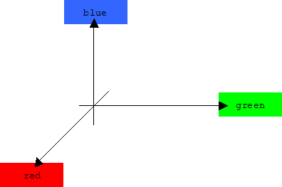
If we use bytes to represent color amounts, then the values along each axis ranges from 0 to 255. The origin, (0, 0, 0), represents black, (255, 255, 255) represents white, (255, 255, 0) represents yellow, (255, 0, 255) represents purple, and (0, 255, 255) represents a blue-green turquoise color.
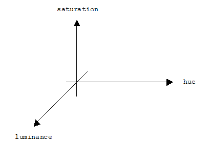
A color can also be regarded as a three dimensional point in which the x, y, and z coordinates represent hue (electromagnetic frequency), saturation (grayness), and luminance (brightness), respectively:
We could represent a color as an object consisting of three bytes, but the Win32 API represents a colors as a 32-bit binary word, instead:
typedef unsigned COLORREF;
The high order byte of a color is always 0. The amount of red is the low order byte, the amount of green is byte two, and the amount of blue is byte three. Using hexadecimal notation (1 byte = 2 hex digits) we can represent a color as the number:
0x00bbggrr
We can extract these bytes using global functions defined by the Win32 API:
BYTE GetRValue(COLORREF color);
BYTE GetGValue(COLORREF color);
BYTE GetBValue(COLORREF color);
The Win32 API also provides a convenient macro function for creating colors:
COLORREF RGB(BYTE red, BYTE green, BYTE blue);
4.7
Paint
1.0
A paint program allows users to set pixels on a canvas using the mouse. Dragging the mouse across the canvas creates a trail of colored pixels much the same way dragging a paint brush across a real canvas creates a stroke of color.
Version 1.0 of Paint is a typical paint program. A special [Brush]/[Width] pop-up menu allows users to set the width of the path created by dragging the mouse to one, three, or five pixels:
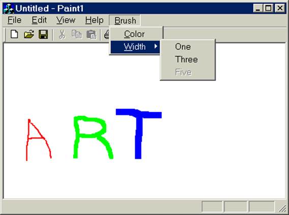
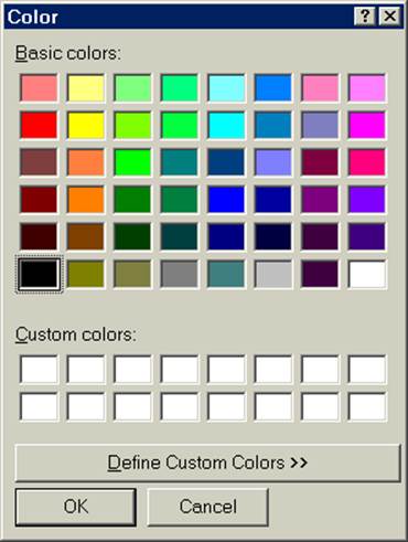
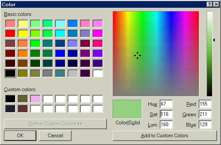
Users can also create custom colors using this dialog box:
Clicking the right mouse button erases the canvas (sets all pixels to white). Be careful. If the version 1.0 Paint window is covered by another window, then the user's work will be lost. Also, version 1.0 doesn't allow users to save their work. (Users can save screen snapshots.) These problems will be solved in version 2.0.
4.7.1 Implementation
We begin by using the App Wizard to create a single document application. All default settings are accepted.
Step 1: Use the MFC App Wizard to create a single document application named Paint1. Accept all of the defaults offered by the wizard.
Instances of the Paint view class encapsulate variables that hold the current brush width, color, and sample point.
Step 2: Add three member variables to the CPaint1View class: brushWidth of type int, color of type COLORREF, and next of type CPoint. These variables should be initialized in the constructor.
Here's a partial listing of the view class that shows the declaration of these three member variables.
class CPaint1View : public CView
{
private:
int brushWidth;
COLORREF color;
CPoint next;
// etc.
};
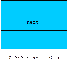
The CPoint, next, holds the coordinates of the next pixel that will be set in view's bitmap (i.e., the "canvas"). The color of the pixel is held in the color variable. Actually, next is just the center of a rectangular patch of pixels that will set in the current color; brushWidth is the height and width of this patch:
Of course these variables need to be initialized in the view constructor. We arbitrarily set the color to red and the brush width to three. We use the constructor's initializer list to specify that the CPoint, next, should be initialized by calling the CPoint constructor that allows the programmer to specify the x and y coordinates. (Otherwise, the default constructor will be used.) We purposely choose off-canvas coordinates (-100, -100). This will prevent a pixel patch from being drawn before the mouse has been touched.
CPaint1View::CPaint1View ()
: next(-100, -100) // next is initially off-canvas
{
brushWidth = 3;
color = RGB(255, 0, 0); // initially
red
}
4.7.2 OnDraw()
OnDraw() uses an outer for-loop to draw the rows of the pixel patch centered around the next point. An inner for-loop draws the columns within each row.
Step 3: Add lines to the OnDraw() function so that it sets a patch of pixels on the canvas.
Here is a complete listing:
void CPaint1View::OnDraw(CDC* pDC)
{
CPaint1Doc* pDoc = GetDocument();
ASSERT_VALID(pDoc);
for(int i = -brushWidth; i <=
brushWidth; i++)
for(int j = -brushWidth; j <=
brushWidth; j++)
pDC->SetPixel(next.x + i,
next.y + j, color);
}
4.7.3 Mouse Movement
The operating system periodically samples the position of the mouse. If the position has changed since the last sample, then a WM_MOUSEMOVE message is sent to the application. This message includes the sampled point as well as a status word. Five predefined masks indicate the significance of the bits in the status word:
MK_CONTROL Set if
the CTRL key is down.
MK_LBUTTON Set if the left mouse
button is down.
MK_MBUTTON Set if the middle mouse
button is down.
MK_RBUTTON Set if the right mouse
button is down.
MK_SHIFT Set if the SHIFT key is
down.
We can use the Class Wizard to add a handler to the view class that will automatically be called when a WM_MOUSEMOVE message is received.
Step 4: Use the [Class Wizard]/[Message Maps] dialog to add a handler to the view class for the WM_MOUSEMOVE message. This function assigns the mouse position to the next variable, then invalidates the screen.
The sampled mouse point and the status word are passed to the handler. We can determine if the mouse is being dragged (i.e., moved while holding the left mouse button down) by taking a bitwise conjunction of the status word and the MK_LBUTTON mask. If so, the sampled point is copied into the next member variable. Finally, we need to force a call to the OnDraw() function:
void CPaint1View::OnMouseMove(UINT nFlags, CPoint point)
{
if (nFlags & MK_LBUTTON)
{
next = point;
// call OnDraw(?)
}
CView::OnMouseMove(nFlags, point);
}
4.7.4 Invalidating the View
Unfortunately, calling the OnDraw() function directly won't work. To understand why, we must first understand the seemingly roundabout way the operating system repaints windows.
Each time a window is resized or uncovered, the operating system marks the region of the screen corresponding to the window as invalid. If there are no pending requests to repaint the window in the message queue, then the operating system requests one by sending a WM_PAINT message to the application. The WM_PAINT message is handled by CView's OnPaint() function, which creates a special type of device context, then passes it to the OnDraw() function:
void CView::OnPaint()
{
CPaintDC dc(this);
OnPrepareDC(&dc);
OnDraw(&dc);
}
The CPaintDC class is derived from CDC. In addition to the features inherited from CDC, a CPaintDC instance has two extra member variables:
class CPaintDC: public CDC
{
protected:
HWND m_hWnd; // handle to a window
public:
PAINTSTRUCT m_ps; // the invalid region
// etc.
};
The first member variable is a handle to the window to be repainted, the second member variable is a paint structure. A paint structure specifies the invalid portion of the window. Recall that this was determined by the operating system and may be the entire window or just part of the window. Although all of the instructions in the OnDraw() function will be executed when it is called by OnPaint(), only the portion of the screen corresponding to the invalid region will be updated. This means the operating system only repaints those windows or parts of windows that need to be repainted.
An application can declare one of its windows to be invalid by calling the window's Invalidate() function. The Invalidate() function marks the entire window as invalid and requests a repaint.
void CWnd::Invalidate(BOOL bErase = TRUE);
Where bErase indicates if the background should be erased before the repaint.
To complete our mouse movement handler, we need to add a call to Invalidate() after the sampled point is saved. In our case we call Invalidate(FALSE). Instead of starting out with a blank canvas, which would erase the entire painting, OnDraw() will start with a dirty canvas; i.e., a canvas with the earlier sampled pixels still colored.
void CPaint1View::OnMouseMove(UINT nFlags, CPoint point)
{
if (nFlags & MK_LBUTTON)
{
next = point;
Invalidate(FALSE);
}
CView::OnMouseMove(nFlags, point);
}
4.7.5 Erasing the Painting
Erasing a drawing is simple. When the right mouse button goes down, the operating system sends a WM_RBUTTONDOWN message to the application. We can use the Class Wizard to add a handler for this message to the view class.
Step 5:
i. Use the [Class Wizard]/[Message Maps] dialog to add a handler to the view for the WM_RBUTTONDOWN message.
ii. This function sets the next member variable to off screen coordinates, then invalidates the view.
iii. Build and test the application.
Our handler parks the next member variable at an off-canvas location, then calls the Invalidate() function with the default TRUE parameter. A blank canvas is passed to OnDraw(). Here's a complete listing:
void CPaint1View::OnRButtonDown(UINT nFlags, CPoint point)
{
next.x = -100;
next.y = -100;
Invalidate();
CView::OnRButtonDown(nFlags, point);
}
4.7.6 Inadvertently Erasing the
Painting
At this point it might be useful to understand the reason behind the main flaw in version 1.0 of Paint: each time the window is resized or uncovered, the painting is erased except for the last pixel. This happens because when the window is resized or uncovered, the operating system invalidates the window. This forces a call to OnDraw(). Unfortunately, our implementation only draws a single pixel patch. Namely, the one centered around the last samples mouse position.
To get a better feel for this repaint mechanism, the reader should use the Paint program to create a painting, drag any other window over a portion of the Paint window, then bring the Paint window to the front by clicking on it. Notice that the portion of the painting that was under the other window has been erased.
Version 2.0 of the Paint program, which will be introduced in the next chapter, will show how this defect can be corrected.
4.7.7 Changing the Brush Color
Users change brush color using the [Brush]/[Color] menu item.
Step 6:
i. Use the menu editor to add a [Brush] menu to the main frame menu.
ii. Add an entry under this menu called [Color]. Make sure you add a shortcut key and a tooltip.
Because the menu bar is associated with the application frame, the messages menu items send can be handled by nearly all of the application classes. In our case we must take care to insure that we place the handler in the view class.
Step 7:
i. Use the [Class Wizard]/[Message Maps] dialog to add a handler for the [Brush]/[Color] menu item to the view class.
ii. The handler should create, display, then read a [Color] dialog.
iii. Build and test the application.
The [Brush]/[Color] handler creates a color dialog object, then calls the dialog's DoModal() member function. This causes the dialog box to appear on the screen. Only when the dialog's [OK] or [Cancel] buttons are clicked will the DoModal() function terminate and return control to the handler. At this point we can discover the selected color selected by calling the dialog's GetColor() member function. Here's a listing:
void CPaint1View::OnBrushColor()
{
CColorDialog cdg; // create dialog
box
cdg.DoModal(); // display dialog box
color = cdg.GetColor(); // get selected
color
}
Dialog boxes will be discussed in detail later in this chapter.
4.7.8 Changing the Brush Width
Users change the brush width with a pop-up menu that is displayed when the mouse rolls over the [Brush]/[Width] menu item. The pop-up menu contains three choices: [One], [Three], and [Five].
Step 8:
i. Use the menu editor to add a pop-up menu called [Width] to the [Brush] menu.
ii. Add three items under the [Width] menu: [Width]/[One], [Width]/[Three], and [Width]/[Five].
As we have seen, a menu item fires two messages. Just before it is displayed, the UPDATE_COMMAND_UI message is sent. Handling this message gives programmers an opportunity to disable or check the menu item. After the menu item is selected, the COMMAND message is sent. We handle both of these messages in the view class.
Step 9:
i. Use the [Class Wizard]/[Message Maps] dialog to add to the view class handlers for the COMMAND and UPDATE_COMMAND_UI messages sent by these menu items.
ii. The command handlers should set the brush width to the corresponding number (i.e., 1, 3, or 5).
iii. The UPDATE handlers should disable the appropriate menu item when the brush width has the corresponding value.
iv. Build and test the application.
Here is a listing for the [Brush]/[Width]/[Five] menu command handler. It simply sets the brushWidth member variable:
void CPaint1View::OnBrushWidthFive()
{
brushWidth = 5;
}
Here is a listing for handler that disables the [Brush]/[Width]/[Five] menu item when the brush width is 5:
void CPaint1View::OnUpdateBrushWidthFive(CCmdUI* pCmdUI)
{
if (brushWidth == 5)
pCmdUI->Enable(FALSE);
}
4.8
Draw
1.0
A drawing program allows users to create shapes and arrange them on the canvas by dragging them with the mouse. Drawing is different from painting, because the shapes are objects, not simply patches of colored pixels on a canvas. Shape objects have properties that we can inspect and modify. In addition to graphical properties such as size, position, and color, a shape can have physical properties such as mass, volume, temperature, etc. As such, drawing programs are the starting point for geometric modeling and computer aided design..
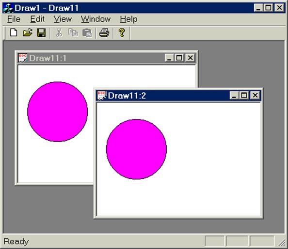
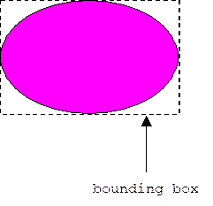
Version 1.0 of our Draw program is nothing more than an experiment. Version 2.0— a usable extension of version 1.0—will be presented in the next chapter. Version 1.0 is a multi-document application that allows users to drag a single elliptical shape around the view window:
Right mouse clicking on the shape, or selecting [Shape] from the [Edit] menu displays the custom [Shape Properties] dialog box:
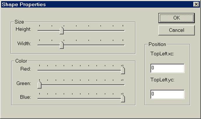
Using this dialog users can modify the size, color, and position of the shape.
4.8.1 Design
The Draw program employs the Document-View architecture. The duty of the document (CDraw1Doc) will be to maintain the logical representation of some geometric model being edited by the user. Alternatively, we could have made the document the geometrical model instead of the manager of the model, but when models get more complex in version 2.0, it will turn out that management duties get more complex. Mixing management duties with geometric modeling duties would limit the reusability of these models in applications with different management requirements.
In version 1.0, the model consists of a single shape, which is an instance of a custom Shape class. The dimensions of a shape's bounding box (i.e., the smallest rectangle that circumscribes the shape) will be inherited from a CRect base class. In addition, a shape encapsulates its current color and provides member functions for moving and resizing itself, as well as plotting itself in a device context. Of course users won't get to call these functions directly. Instead, they will be called by like-named functions in the document.
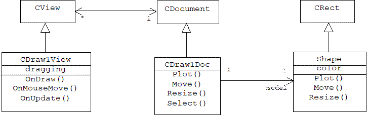
Of course every document may have multiple open views (CDraw1View). The view with input focus listens for mouse move messages coming from the mouse. If the left mouse button is being held down, a Boolean flag called dragging is set to true and the document's Move() function is called. This function notifies the other views by indirectly calling their OnUpdate() functions. OnUpdate() invalidates the view window, forcing a call to OnDraw(), which simply asks the document to plot its model in the current device context.
In addition, our documents support serialization and deserialization so users can save changes in the color, size, and position of the shape. This isn't so interesting in version 1.0, but it will be important in version 2.0, which allows users to create complex composite shapes.
4.8.2 Implementation
We begin by using the MFC AppWizard to create a default application named Draw1:
Step 1: Use the MFC App Wizard to create a multiple document application named Draw1. Accept all of the defaults offered by the wizard.
4.8.3 The Shape Class
Next, we add a custom Shape class to our project.
Step 2: Use the [Insert]/[New Class] dialog to add a generic class named Shape to the project.
A shape is characterized by two things: its bounding box and its color:
We specify the color of a shape with a COLORREF attribute. We could, of course, specify a shape's bounding box with a CRect attribute. If instead we declare Shape to be derived from CRect, then we can regard a shape's inherited CRect attributes as a description of its bounding box. This is a violation of the Type Conformance Principle:
If S is a subclass of T, then an instance of S can be used in any context where an instance of T is expected.
There are certainly lots of things that are true of rectangles that aren't true of shapes in general. If, on the other hand, we allow this violation, then we can use shape pointers in many context where CRect pointers are used. This will prove to be very handy later on when we can simply call the inherited CRect functions to move and resize shapes.
Step 3:
i. The Shape class should be derived from the CRect class.
ii. Add a protected member variable called color of type COLORREF. This variable should be initialized in the constructor along with the left, right, top, and bottom variables inherited from CRect.
iii. Add "getter" functions that will allow clients to extract the amount of red, green, and blue in the color, and a "setter" function that will allow clients to redefine the color.
Here is a partial listing of the Shape declaration:
class Shape: public CRect
{
public:
Shape(int h = 100, int w = 100, int
xc = 0, int yc = 0)
: CRect(xc, yc, xc + w, yc + h)
{
color = RGB(255, 0, 255); // purple
for starters
NormalizeRect();
}
virtual ~Shape() {}
void SetColor(int r, int g, int b)
{
color = RGB(r, g, b);
}
int GetRed() { return GetRValue(color);
}
int GetGreen() { return
GetGValue(color); }
int GetBlue() { return
GetBValue(color); }
protected:
COLORREF color;
// etc.
};
Notice that the Shape constructor expects four parameters specifying the height, width, and upper left corner of its bounding box. By supplying default arguments, the Shape constructor can be called with fewer parameters. In particular, if the upper left corner of the bounding box isn't specified, then it is assumed to be the origin. By default, all shapes are purple. Clients will need to call SetColor() to change colors.
By default, a constructor calls the default constructor of its base class to initialize inherited member variables. This isn't good for us. We need to call the CRect constructor that allows us to specify the upper left corner and lower right corner of a rectangle. To get C++ to call a special constructor, the call must be placed in the initializer list, which occurs between the header and body of the constructor.
We need to be able to move, resize, and plot shapes, so we next add member functions to perform these duties.
Step 4:
i. Add virtual member functions to the Shape class that allow clients to move, resize, and draw shapes. Moving and resizing call appropriate functions inherited from the CRect base class.
ii. Drawing a shape requires two functions: a public Plot() function that calls a protected virtual Draw() function. For now, the Draw() function simply draws an ellipse in its device context parameter.
Moving a shape, s, to a particular point, p, means setting the upper left corner of its bounding box to p, and setting the lower right corner to (p.x + width, p.y + height). This can be done by calling the SetRect() function inherited from the CRect base class.
Resizing a shape to a new height h and width w, means moving the lower edge of its bounding box by w - width, and moving the right edge of the bounding box by h - height. (Of course h and w can be negative numbers.) This can be done by calling the InflateRect() function inherited from the CRect base class.
Here is a partial listing:
class Shape: public CRect
{
public:
virtual void Move(CPoint p)
{
SetRect(p.x, p.y, p.x + Width(), p.y
+ Height());
}
virtual void Resize(int height, int
width)
{
InflateRect(0, 0, width - Width(),
height - Height());
}
void Plot(CDC* pDC);
protected:
virtual void Draw(CDC* pDC) {
pDC->Ellipse(this); } // for now
// etc.
};
4.8.3.1 Exchanging Tools
The Shape Plot() function will call the protected Draw() function, which simply passes a pointer to itself to the Ellipse() function of some specified device context. Since a pointer to a Shape is also a pointer to a CRect, this function draws the largest ellipse it can fit into the shape regarded as a bounding box.
Why do we need a Plot() function to call the Draw() function? Recall that a device context comes equipped with a blank canvas (i.e., a bitmap) and a set of drawing tools: pen, brush, font, etc. The default brush automatically paints the inside of polygons and ellipses white. This isn't what we want. Instead, we want the inside of our ellipse to be the color specified by the shape's color attribute. Therefore, before we call Draw(), we must replace the device context's white brush with a brush that uses the color of the shape.
Fortunately, the CDC class provides a member function called SelectObject() that can be used to swap drawing tools, but there is one complication. The rule in Windows is that the creator of a drawing tool is responsible for destroying the tool when it is no longer needed. If a programmer creates a new brush, then the programmer must be sure the brush is destroyed when he is finished using it. The brush originally supplied with the device context is created by the operating system, and therefore must be destroyed by the operating system. Presumably, this happens when the operating system destroys the device context. This implies that the original brush must be given back to the device context after the call to Draw().
Fortunately, the SelectObject() function not only trades a new tool for an old one, it returns a pointer to the old tool. If we save this pointer, we can call SelectObject() after Draw() to replace the new tool by the old tool. If pDC is a CDC pointer, then this protocol can be implemented as follows:
CBrush *newBrush, *oldBrush;
newBrush = new CBrush(color);
oldBrush = pDC->SelectObject(newBrush);
Draw(pDC);
pDC->SelectObject(oldBrush);
delete newBrush;
Alternatively, newBrush can be a local object rather than a local pointer. The advantage of this is that local objects are automatically created when the function that declares them is called, and they are automatically destroyed when the function terminates, so the calls to new and delete are not needed:
CBrush newBrush, *oldBrush;
oldBrush = pDC->SelectObject(&newBrush);
Draw(pDC);
pDC->SelectObject(oldBrush);
Step 5: Implement the Plot() function in Shape.cpp. Before calling Draw(), this function should temporarily exchange the white brush provided by the device context parameter for a brush that paints in the color of the shape.
Here is a listing:
void Shape::Plot(CDC* pDC)
{
CBrush *newBrush, *oldBrush;
newBrush = new CBrush(color);
oldBrush =
pDC->SelectObject(newBrush);
Draw(pDC);
pDC->SelectObject(oldBrush);
delete newBrush;
}
4.8.4 The Draw1 Document
The document in MFC's Document-View architecture is responsible for managing the application's data. For the Draw program, the data is the model. The Draw document encapsulates the model and provides functions that call the corresponding model functions. These functions also set the modified flag and notify the views.
Step 6:
i. Include Shape.h at the top of Draw1Doc.h.
ii. Add a Shape member variable called model to the document class.
iii. Also, add a CPoint member variable called mouseOffset. This will be used later to implement mouse dragging.
iv. Add a Plot() function that calls the model's Plot() function.
v. Add a Move() function that will be used to drag the model.
vi. Add a Select() function that will initialize the mouseOffset variable.
vii. Add a "getter" function for the model member.
viii. Add a Resize() function that will be used to resize the model..
Here's a listing:
#include "Shape.h"
class CDraw1Doc : public CDocument
{
public:
void Plot(CDC* pDC) { model.Plot(pDC);
}
Shape GetModel() { return model; }
void Select(CPoint p); // set
mouseOffset
void Move(CPoint p); // move model
void Resize(int h, int w);
private:
Shape model;
CPoint mouseOffset;
// etc.
};
4.8.4.1 Serializing the Model
Serializing a shape simply involves inserting all of its attributes (top, bottom, left, right, and color) into an archive. To deserialize a shape we extract these attributes and normailze.
Step 7: Implement the document's serialize function.
Here's a listing:
void CDraw1Doc::Serialize(CArchive& ar)
{
if (ar.IsStoring())
{
ar << model.bottom;
ar << model.top;
ar << model.left;
ar << model.right;
ar << model.GetRed();
ar << model.GetGreen();
ar << model.GetBlue();
}
else
{
ar >> model.bottom;
ar >> model.top;
ar >> model.left;
ar >> model.right;
model.NormalizeRect();
int r, g, b;
ar >> r;
ar >> g;
ar >> b;
model.SetColor(r, g, b);
}
}
4.8.4.2 Moving the Model
Step 8: Implement the document's Move() function.
The document's Move() function is called by the mouse move handler of the current view. Basically, this Move() function calls the model's Move() function, sets the modified flag, then updates all subscribing views.
Unfortunately, the model's Move() function simply sets the top left corner of the model to the indicated point. This can cause the model to jump slightly if the mouse cursor isn't initially near this corner. To compensate, the document's Move() function subtracts the mouse offset (mouseOffset) from the current mouse position, then pass the result to the model's Move() function. The mouse offset is calculated by the document's Select() function, which is called each time the left mouse button is pressed. It simply calculates the difference between the mouse position and the top left corner of the model:
void CDraw1Doc::Select(CPoint p)
{ // p = current mouse position
mouseOffset = p - model.TopLeft();
}
Here is a complete listing of the Move() function:
void CDraw1Doc::Move(CPoint p)
{ // p = current mouse position
model.Move(p - mouseOffset);
SetModifiedFlag(TRUE);
UpdateAllViews(NULL);
}
4.8.4.3 Resizing the Model
Step 9: Implement the document's Resize() function.
The document's Resize() function calls the model's Resize() function, sets the modified flag to true, then notifies all open views. Here's the complete listing:
void CDraw1Doc::Resize(int h, int w)
{ // p = current mouse position
model.Resize(h, w);
SetModifiedFlag(TRUE);
UpdateAllViews(NULL);
}
4.8.5 The Draw1 View
Step 10: Add a private Boolean variable called dragging to the CDraw1View class. This variable is set to false in the constructor. When true, it indicates that the model is being dragged.
Here is a partial listing of the CDraw1View declaration:
class
CDraw1View : public CView
{
protected:
CDraw1View() { dragging = false; }
private:
bool dragging; // = true if mouse in
model
// etc.
};
4.8.5.1 OnDraw
Step 11: Implement OnDraw(). This function simply calls the Plot() function of the associated document.
Here is a listing:
void CDraw1View::OnDraw(CDC* pDC)
{
CDraw1Doc* pDoc = GetDocument();
ASSERT_VALID(pDoc);
pDoc->Plot(pDC);
}
4.8.5.2 Mouse Clicks
We have already seen that the operating system periodically samples the mouse position and sends the application with input focus a WM_MOUSEMOVE message when it discovers the mouse has moved.
In our Draw application we need to know if the user is dragging the mouse, that is, if the user is moving the mouse while holding down the left mouse button. This is easy to figure out, because the WM_MOUSEMOVE message includes the status of the left mouse button (up or down). But the problem is more complicated. We only assume the model is being dragged if the mouse cursor is inside the shape. In other words, if when the left mouse button went down, the cursor was within the model's bounding box.
In addition to sampling the mouse position, single clicking or double clicking the left or right mouse buttons also results in the operating system sending the application with input focus the corresponding message. For example, clicking the left mouse button once causes the application with input focus to receive the WM_LBUTTONDOWN message. The corresponding handler is:
void CWnd::OnLButtonDown(UINT nFlags, CPoint point);
The point parameter indicates the position of the mouse at the time its left button was clicked. The nFlags parameter is a bitwise disjunction of the following status flags:
MK_CONTROL Set if
the CTRL key is down.
MK_LBUTTON Set if the left mouse
button is down.
MK_MBUTTON Set if the middle mouse
button is down.
MK_RBUTTON Set if the right mouse
button is down.
MK_SHIFT Set if
the SHIFT key is down.
Our plan will be to implement this handler so that it determines if the mouse is within the bounding box of the model when the left mouse button initially goes down.
4.8.5.3 Setting the Mouse Offset
Step 12:
i. Use the [Class Wizard]/[Message Maps] dialog to add a handler for the LBUTTONDOWN message to the view class.
ii. This handler initially sets the dragging variable to false.
iii. If the mouse position is inside the model's bounding box, then the mouse position is passed to the document's Select() function (which computes the offset of the mouse from the top left corner of the model) and the dragging flag is set to true.
Hers is a listing:
void CDraw1View::OnLButtonDown(UINT nFlags, CPoint point)
{
dragging = false;
CDraw1Doc* pDoc = GetDocument();
if
(pDoc->GetModel().PtInRect(point))
{
pDoc->Select(point);
dragging = true;
}
CView::OnLButtonDown(nFlags, point);
}
4.8.5.4 Dragging the Model
Step 13:
i. Use the [Class Wizard]/[Message Maps] dialog to add a handler for the MOUSEMOVE message to the view class.
ii. If the dragging flag is set, and if the user is holding down the left mouse button, then the mouse position is passed to the Move() function of the associated model.
Here is a listing:
void CDraw1View::OnMouseMove(UINT nFlags, CPoint point)
{
if (dragging && (nFlags
& MK_LBUTTON))
{
CDraw1Doc* pDoc = GetDocument();
pDoc->Move(point);
}
CView::OnMouseMove(nFlags, point);
}
4.8.5.5 Updating the Views
Step 14: Use the [Class Wizard]/[Message Maps] dialog to add an OnUpdate() function to the view class. This function simply invalidates the entire view window.
Here is a listing:
void CDraw1View::OnUpdate(
CView* pSender, LPARAM lHint, CObject*
pHint)
{
CDraw1Doc* pDoc = GetDocument();
Invalidate();
}
Step 15: Build and test the application.
4.9
Dialog
Boxes
Obtaining numeric or textual input from the user poses a special problem for graphical programs like Draw. There are too many possible inputs to choose from a menu, so we will need to provide an edit box where the input can be typed. But where will we put this edit box? Views in a graphics program are blank canvases, not forms that can hold edit boxes and other controls.
Fortunately, it is easy to add forms to an application, only instead of views, these forms will be dialog boxes. The reader is already familiar with dialog boxes. There are, of course, the file dialogs used by all applications to solicit the name of a file and a directory from the user, the color dialog used by the Paint program to solicit colors from the user, and we have used message dialogs to convey error messages to the user.
Normally, dialog boxes appear in response to a user command. For example, a file dialog appears when the user selects the [File]/[Open] or [File]/[Save As] menu items. A typical dialog box will provide the user with buttons for updating the document ([Apply]), updating the document and dismissing the dialog box ([OK]), and dismissing the dialog without updating the document ([Cancel] or [Hide]).
There are two types of dialog boxes. A modal dialog box prohibits the user from working with the application until it has been dismissed. Modal dialog boxes are created by calling a function that doesn't return control to the application until the dialog box is dismissed. Modal dialogs are useful in situations where it doesn't make sense for the user to keep working until he has made the decision presented by the dialog box.
By contrast, a modeless dialog box allows the user to resume working without dismissing it. In effect, there are two message loops, one that dispatches messages for the dialog box, and another that dispatches messages for the application window. Modeless dialogs are often used as tool bars that must remain handy to the user while working with the application.
We will demonstrate dialog boxes by creating a [Shape Properties] dialog box for our Draw1 application. This dialog box will allow users to change the color, size, and position of the current shape. The dialog box will be summoned by the user either by selecting [Shape] from the [Edit] menu, or by clicking on the shape to be edited with the right mouse button. In the first implementation, the [Shape Properties] dialog will be modal. A modeless version will be presented as a second implementation.
The general steps for adding a dialog box to an application are these:
1. Insert a new dialog resource into the project.
2. Use the Dialog Editor to design the dialog.
3. Use the Class Wizard to declare and implement a wrapper class for the dialog.
4. Provide a menu item the user can select to display the dialog. The menu item handler function should a) create a wrapper for the dialog, b) use document data to initialize the wrapper, c) ask the wrapper to display its body, the system-level dialog, and d) use the wrapper to update the document after the wrapper's body has been dismissed.
Much of what we learned in Chapters 2 and 3 about creating and programming form views is the same for dialog boxes. In particular, a dialog wrapper has member variables that correspond to the states of dialog controls and member functions that handle messages sent by dialog controls. We use the [Class Wizard] to "wire" member variables to dialog controls using DDX/DDV, and to "wire" message handlers to messages using message maps. In the modeless case, we will call UpdateData(TRUE) to transfer control states to member variables and UpdateData(FALSE) to go the other way.
The main difference between dialog boxes and form views is that form views and their wrappers were created for us by the MFC App Wizard. Our job was simply to edit these classes. In the case of a dialog box we must first create both, the dialog resource, and the corresponding wrapper class.
4.9.1 Adding a Modal Dialog to Draw
1.0
Creating a new resource and adding it to a project is done by selecting [Resource ...] from the [Insert] menu. This displays the [Insert Resource] dialog box that presents the different types of resources (menus, dialogs, toolbars, icons, etc.) as a tree control. Although there are many types of dialogs under the [Dialog] node of the tree, we will ignore these and simply select the root of the tree as our resource type, then press the [New] button.
Step 1:
i. Use the [Insert Resource] dialog box to create a generic dialog box resource.
ii. Use the [Dialog Editor] to add five labeled sliders and two labeled edit boxes arranged inside group boxes labeled "Size", "Position", and "Color". Use the screen shot given earlier as a guide. Set the ID of each control to something memorable.
iii. Check the [Tick Marks] and [AutoTicks] check boxes on the [Styles] page of the slider property sheets, and set the [Point] drop down menu to "Top/Left".
iv. Set the caption of the dialog box to "Shape Properties".
Here's a snapshot of the Dialog Editor and the [Shape Properties] dialog box:

Here's a screen shot of the Slider's [Properties]/[Styles] dialog for the [Red] slider:
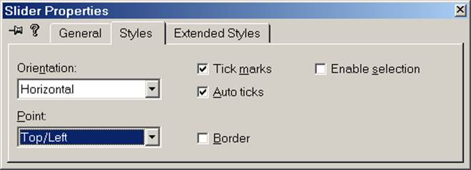
Checking the [Tick marks] box specifies that tick marks are to b`e displayed. Selecting [Top/Left] in the [Point] menu specifies that the tick marks are to be displayed along the top of a horizontal slider or along the left of a vertical slider. Checking the [Auto ticks] check box specifies that a tick mark is to be automatically placed for each increment in the slider's range of values.
As we have mentioned before, the Dialog Editor allows us to graphically define the system class for all "Shape Properties" system dialogs. Each "Shape Properties" dialog box we see on our desktop corresponds to an instance of this system class. Of course all system objects are managed by the operating system. We operate indirectly on system objects through wrappers— application-level C++ objects that delegate client requests to associated system-level objects (the wrapper's body).
Obviously, the MFC App Wizard couldn't have anticipated that we would need a wrapper class for our dialog boxes, so none was provided. However, if we invoke the Class Wizard from the dialog box's shortcut menu, the Class Wizard will immediately note the absence of a wrapper class for the newly created resource and will ask the user to allow it to create one. If the user consents, a new class will be added to the project. This new class will be derived from MFC's CDialog class, which is itself derived from CWnd. CDialog is the base class for all dialog wrappers.
Step 2: Select "Class Wizard" from the dialog box's shortcut menu. The Class Wizard will first ask if you want to create a new class derived from CDialog to serve as a wrapper for the new dialog resource. Choose "CShapeProps" as the name of the new wrapper class, then click the [OK] button.
The following class diagram shows the new wrapper class and its relationship to MFC's CDialog and CWnd classes as well as the system-level dialog class:
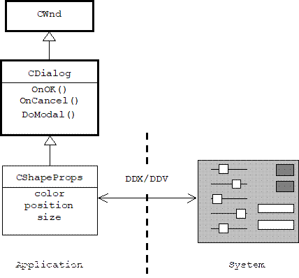
Note that CShapeProps inherits handlers for the [OK] and [CANCEL] buttons. In fact, these already do the right thing for modal dialogs. Namely, OnOK() calls UpdateData(TRUE), then dismisses the system-level dialog. OnCancel() simply dismisses the system-level dialog without calling UpdateData(TRUE). As we shall see, the inherited DoModal() function creates, initializes, and displays the system-level dialog, only terminating after the user dismisses the dialog.
Our plan is to use the Class Wizard's [Member Variables] dialog to add member variables corresponding to the properties of the current shape (color, size, and position) that are wired to the sliders and edit boxes in the dialog box. We have already seen that this is simple for edit controls. Unfortunately, MFC support for adjustment controls such as sliders and scroll bars is comparatively immature.
The Class Wizard's [Member Variables] dialog allows us to associate member variables with dialog controls. Each variable is created using the [Add Member Variable] dialog, which lets us choose between two categories of member variable types: value and control. Choosing "control" creates a member variable wrapper for the control— in effect, a member variable that represents the entire control. Choosing "value" creates a member variable that represents the state of the control— usually a simple type such as a string or a number.
Until now we haven't felt the need to create member wrappers for individual controls on a form or a dialog. In most of the cases we have seen a simple state variable was sufficient, although in some cases, as with the Stack Calculator's list box or the Piano's scroll bar in Chapter 3, we have used CWnd's GetDlgItem() function to create temporary wrapper objects for controls. We could follow this same strategy with our slider controls, but for contrast, we will use member wrappers instead.
Step 3:
i. Use the [Class Wizard]/[Member Variables] to add integer valued member variables for each of the edit boxes called m_tlxc (top left x-coordinate), m_tlyc (top left y-coordinate).
ii. Also add member variables for each of the sliders called m_red, m_blue, m_green, m_height, and m_width, but select "Control" from the [Category] drop down list in the [Add Member Variable] dialog box. This will automatically set the type of these variables to CSliderCtrl.
Here's a snapshot of the [Class Wizard]/[Member Variables] dialog after adding variables corresponding to controls:
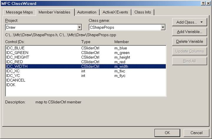
Of course CShapeProps clients won't want to infer the size and color selected by the user by querying the member wrappers nested inside the dialog wrapper. Instead, we will add public member variables to CShapeProps corresponding to color and size. Unfortunately, the Class Wizard won't wire these variables to the corresponding controls, this will be our job.
Step 4: Manually add public integer member variables named red, green, blue, height, and width to the CShapeProps class. Initialize these variables to 100 in the constructor. Later, we will program these variables to hold the pointer position of the corresponding slider controls.
In many cases member wrappers are easier to program, but they are more dangerous, because asking a wrapper to delegate a request to its associated control before the operating system has had a chance to create the control will cause the program to crash. For example, before initializing the sliders, we must wait for the operating system to send us the WM_INITDIALOG message, which indicates that the system-level dialog has been created and is about to be displayed.
Step 5:
i. Use the [Class Wizard]/[Message Maps] dialog to add a handler to the CShapeProps class for the WM_INITDIALOG message.
ii. Implement this function so that it sets the range, tic frequency, and thumb pointer position for each slider.
Here's the declaration of CShapeProps from ShapeProps.h. The color and size variables added by us are shown in boldface. Note the member variables and member functions added by the Class Wizard:
class CShapeProps : public CDialog
{
public:
int red, green, blue; // shape color
int height, width; // shape size
//Dialog Data
//{{AFX_DATA(CShapeProps)
enum { IDD =
IDD_SHAPEPROPS };
CSliderCtrl m_width;
CSliderCtrl m_red;
CSliderCtrl m_height;
CSliderCtrl m_green;
CSliderCtrl m_blue;
int m_tlxc;
int m_tlyc;
//}}AFX_DATA
protected:
//{{AFX_VIRTUAL(CShapeProps)
virtual void
DoDataExchange(CDataExchange* pDX);
//}}AFX_VIRTUAL
// Generated
message map functions
//{{AFX_MSG(CShapeProps)
virtual BOOL
OnInitDialog();
//}}AFX_MSG
DECLARE_MESSAGE_MAP()
};
BOOL CShapeProps::OnInitDialog()
{
CDialog::OnInitDialog();
// init Red slider:
m_red.SetRange(0, 255);
m_red.SetTicFreq(25);
m_red.SetPos(red);
// init Green and Blue sliders ...
// init Height slider:
m_height.SetRange(10, 350);
m_height.SetTicFreq(50);
m_height.SetPos(height);
// init Width slider ...
};
Step 6: Enhance CShapeProps::DoDataExchange() so that it transfers the slider pointer positions to the corresponding integer member variables.
As we mentioned earlier, the Class Wizard has already "wired" the sliders to the CSliderCtrl member variables. Recall that the wiring is done by implementing the DoDataExchange() function, which is called by UpdateData(), and which in turn calls various low-level DDX and DDV functions. It's a simple matter for us to add code to this function that transfers the slider pointer positions to the corresponding color and size member variables. Of course we only do this when data is being transferred from the dialog to the wrapper (i.e., when UpdateData(TRUE) is called):
void CShapeProps::DoDataExchange(CDataExchange* pDX)
{
// code generated by the Class Wizard
here, and then:
if (pDX->m_bSaveAndValidate) //
UpdateData(TRUE)
{
red = m_red.GetPos();
blue = m_blue.GetPos();
green = m_green.GetPos();
height = m_height.GetPos();
width = m_width.GetPos();
}
}
4.9.2 Summoning the Dialog
Next, we must provide the user with some way of summoning the [Shape Properties] dialog box to edit the current shape. Typically, this is done by selecting a menu item.
Step 7: Add a [Shape] item to the [Edit] menu.
In our earlier examples, menu handlers were placed in the view class. Because menus and toolbars are associated with the application window rather than a particular view or dialog box, the messages they send— which are called commands— are routed: first to the main frame, then to the child frame, next to the view, next to the document, and last to any dialog. If one of these objects chooses to handle the command, then the command is consumed and not passed to the next object along the route. Note that all of these classes are derived from the class CCmdTarget, which is simply the base class of all objects that can handle command messages.
Until now our view classes have been assigned both presentation and controller responsibilities. Even in the Draw application, the view is responsible for handling mouse messages. However, as manager of the model and current shape, the document is in the best position to handle [Shapes] menu commands.
Step 8: Add a public handler for the [Edit]/[Shape] menu item to the CDraw1Doc class. Implement handler.
The handler for the [Shapes]/[Edit] menu item creates, initializes, and displays the [Shape Properties] dialog box. When the dialog box is dismissed, the handler updates the model.
For modal dialogs it is sufficient to create a wrapper as a local member variable. We initialize the member variables of the wrapper using the size, color, and position of the current shape. Next, DoModal() is called. This function creates the system-level dialog, calls UpdateData(FALSE) to initialize it, then displays it. DoModal() only returns when the user dismisses the dialog by clicking the [OK] or [Cancel] buttons. This is why the user can't continue working with the application before dismissing the dialog, the application's message loop won't resume until the call to DoModal() terminates.
If the user dismisses the dialog by clicking the [OK] button then the handler for this button calls UpdateData(TRUE) before dismissing the dialog. In this case the slider pointer positions and the edit box entries will be transferred to the wrapper. If the user dismisses the dialog by clicking the [Cancel] button, then the dialog is dismissed without the call to UpdateData(). In this case the wrapper member variable values are unchanged. In both cases it makes sense to use these values to update the current shape. Here's a complete listing for the [Edit]/[Shape] menu handler:
void CDraw1Doc::OnEditShape()
{
CShapeProps dialog; // create a local
wrapper
dialog.blue = model.GetBlue();
dialog.green = model.GetGreen();
dialog.red = model.GetRed();
dialog.height = model.Height();
dialog.width = model.Width();
dialog.m_tlxc = model.TopLeft().x;
dialog.m_tlyc = model.TopLeft().y;
dialog.DoModal();
model.SetColor(dialog.red,
dialog.green, dialog.blue);
model.Resize(dialog.height,
dialog.width);
model.Move(CPoint(dialog.m_tlxc,
dialog.m_tlyc));
SetModifiedFlag(TRUE);
UpdateAllViews(NULL);
}
Because the OnEditShape() function refers to the CShapeProps class, we have introduced a dependency in the Draw1Doc.cpp file on the ShapeProps.h file. We can resolve this dependency by including ShapeProps.h at the top of Draw1Doc.cpp:
#include "ShapeProps.h"
Although not necessary, it will make the user's life easier if he can summon the [Shape Properties] dialog by right clicking on a shape.
Step 9:
i. Add a handler for the WM_RBUTTONDOWN message to the view class. Implement the handler.
ii. Change the visibility of CDrawDoc's OnEditShape() from protected to public.
iii. Build and test the application.
Here's a listing:
void CDraw1View::OnRButtonDown(UINT nFlags, CPoint point)
{
CDraw1Doc* pDoc = GetDocument();
if
(pDoc->GetModel().PtInRect(point))
pDoc->OnEditShape();
CView::OnRButtonDown(nFlags, point);
}
4.9.3 Modeless Dialog Boxes
The modal version of the [Shape Properties] dialog is inconvenient for experimenting with different colors and sizes, because it must be dismissed before the updates to the document are made, then re-summoned to make a subsequent adjustment.
A modeless [Shape Properties] dialog box allows the user to adjust its controls, then click the [Apply] button (the former [OK] button) to update the current shape without dismissing the dialog. If the dialog box is in the way, the user can click on the dialog's [Hide] button (the former [Cancel] button) to dismiss it.
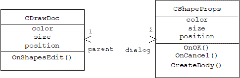
Of course this implies that the wrapper for the dialog box can't be a local variable that disappears as soon as a menu handler function terminates. The wrapper for a modeless dialog needs a longer lifespan, so we will introduce a pointer to a wrapper as a member variable in the document class. When the [Shapes]/[Edit] menu item handler is called, it will simply instruct the dialog pointer to create and display its body (i.e. a system-level dialog). Of course the [OK] and [Cancel] button handlers inherited from the CDialog base class dismiss the dialog. This won't do for the modeless version, so we will need to use the Class Wizard to add new button handlers to the CShapeProps class. The [Cancel] button handler will ask the operating system to destroy its body. The [OK] button handler will update the associated document. The following class diagram shows the bi-directional association between document and dialog:
Of course the bi-directional dependency introduces a mutual dependency between the header files where these classes are declared. we must take care in resolving this dependency.
4.9.3.1 Dialog Wrapper Modifications
We begin by modifying the CShapeProps class.
Step 1: Add a CDrawDoc pointer member to the CShapeProps class called "parent". This pointer should be initialized to 0 in the CDrawDoc default constructor.
Here's a partial listing of the CSahpeProps class showing the new member variable:
class CShapeProps : public CDialog
{
public:
CDrawDoc* parent;
// etc.
};
The reference to CDrawDoc* in ShapeProps.h introduces a dependency on DrawDoc.h which can be resolved by including DrawDoc.h at the top of ShapeProps.h:
#include "DrawDoc.h"
Of course we need a constructor that initializes parent to something other than 0.
Step 2: Add a CDrawDoc constructor that initializes the parent pointer.
Our constructor will take a pointer to the parent CDrawDoc as a parameter. Don't forget to add a prototype for this constructor to the CShapeProps class declaration.
CShapeProps::CShapeProps(CDrawDoc* p)
{
parent = p;
m_tlxc = 0;
m_tlyc = 0;
}
Next, we must declare and implement a CShapeProps member function called CreateBody() that the document can call when it wants the dialog wrapper to ask the operating system to create and display an associated system-level dialog. Fortunately, the CDialog class provides a member function called Create() that does just this.
When we ask the operating system to create a system object, we need to specify the system class the object instantiates. As we mentioned in Chapter 2, there is a rough analogy between handles and system objects, and a rough analogy between resource identifiers and system classes. Following this analogy, the CDialog::Create() function expects the resource identifier of the [Shape Properties] dialog as input. If successful, a system-level dialog will be created and displayed, and a handle to this object will be assigned to the m_hWnd member variable inherited from the CWnd base class.
Notice that the Class Wizard generated the declaration of an anonymous enumeration nested inside the CShapeProps class:
class CShapeProps : public CDialog
{
public:
int red, green, blue; // shape color
int height, width; // shape size
//Dialog Data
//{{AFX_DATA(CShapeProps)
enum { IDD =
IDD_SHAPEPROPS };
//
etc.
};
In effect, anonymous nested enumerations are a quick way to introduce static integer constants into a class. That's the purpose of the enumeration above, which introduces IDD as a fixed name for IDD_SHAPEPROPS, the resource ID number we assigned to the [Shape Properties] dialog box when we designed it in the Dialog Editor. This means our CreateBody() function can simply call:
Create(IDD);
UpdateData(FALSE);
Unfortunately, attempting to create body will cause the program to crash if the dialog wrapper already has a body. This could happen, for example, if the user selects [Shapes]/[Edit] even though the [Shape Properties] dialog for the current shape is already on the desktop.
Of course the m_hWnd member variable inherited from the CWnd base class is a public variable. Our CreateBody() function could simply check to see if this variable contains the handle of a system-level dialog that exists. Unfortunately, when a system-level window stops existing, neither the application nor the operating system may bother to update m_hWnd. However, CWnd provides a member function called GetSafeHwnd() that updates and returns m_hWnd. If the associated system-level window doesn't exist, GetSafeHwnd() returns NULL.
Step 3: Add a member function that creates a system-level dialog box.
Here is the complete implementation:
void CShapeProps::CreateBody()
{
if (GetSafeHwnd() == NULL) // no body
exists
{
Create(IDD);
UpdateData(FALSE);
}
}
As we mentioned earlier, the [OK] and [Cancel] button handlers inherited from the CDialog base class both dismiss the dialog box. This won't do for modeless dialog boxes, so we must provide our own handlers for these buttons.
Step 4:
i. Use the Class Wizard to add handlers for the BN_CLICKED message sent by the IDOK and IDCANCEL buttons.
ii. Implement the handler for IDOK so that it updates its parent.
iii. Implement the handler for IDCANCEL so that it destroys the system-level dialog.
We might think that the OnCancel() function inherited from CDialog will work for modeless dialogs, after all, it does destroy the system-level dialog. Unfortunately, the destruction is so complete, that the user will never be able to summon the dialog again! Instead, the modeless version of OnCancel() simply calls the DestroyWindow() function inherited from CWnd:
void CShapeProps::OnCancel()
{
if (parent) // modeless case
DestroyWindow();
else //modal case
CDialog::OnCancel();
}
The modeless version of OnOK() updates the wrapper member variables by calling UpdateData(TRUE), then updates the current shape of the associated document. This is the part of CShapeProps where the parent pointer to the document is needed:
void CShapeProps::OnOK()
{
if (parent) // modeless case
{
UpdateData(TRUE);
parent->Move(CPoint(m_tlxc,
m_tlyc) + parent->mouseOffset);
parent->Resize(height, width);
parent->SetColor(red, green,
blue);
parent->SetModifiedFlag(TRUE);
parent->UpdateAllViews(NULL);
}
else //modal case
CDialog::OnOK();
}
4.9.3.2 Dialog Modifications
Modeless dialogs require one crucial change to the dialog resource. For some unknown reason dialog resources have a visibility property with a default value of FALSE. This seems to have no effect on modal dialogs, but in the case of a modeless dialog it causes the dialog box to be invisible! This can cause hours of frustration for programmers, so it is imperative that the value of this property be set to TRUE in the dialog resources property sheet.
Step 5: Use the Dialog Editor the change the caption of the [OK] button to "Apply" and the caption of the [Cancel] button to "Hide". Important: Check the [Visible] box on the [More Styles] page of the dialog box's property sheet.
4.9.3.3 Document Modifications
Finally, we need to make a few changes to the document class.
Step 6: Add a CShapeProps pointer member called "dialog" to the CDrawDoc class. This pointer should be initialized to 0 by the constructor and deleted by the destructor.
class CDrawDoc : public CDocument
{
private:
Shape model;
CShapeProps* dialog; // modeless dialog
// etc.
};
Adding a CShapeProps pointer to CDrawDoc introduces a dependency in DrawDoc.h on ShapeProps.h. Of course we have already seen that DrawDoc.cpp depends on ShapeProps.h and that ShapeProps.h depends on DrawDoc.h. We resolved the first dependency by including ShapeProps.h at the top of DrawDoc.cpp. But the second dependency is one direction of a bi-directional dependency. We can't resolve both directions by including one file in the other. Slow witted pre-processors might get caught in an infinite loop trying to execute the include statements.
Since we already resolved the dependency of ShapeProps.h on DrawDoc.h by including DrawDoc.h in ShapeProps.h, we can't resolve the dependency of DrawDoc.h on ShapeProps.h with another include statement. Instead, this dependency must be resolved with a forward declaration placed at the top of DrawDoc.h:
class CShapeProps; // forward reference
This works as long as DrawDoc.h only refers to CShapeProps pointers without calling any CShapeProps member functions or accessing any CShapeProps member variables. Instead, this work must be moved to DrawDoc.cpp, where the entire declaration of CShapeProps is available to the compiler.
To finish, we need to alter the [Shapes]/[Edit] menu item handler in the CDrawDoc class.
Step 7: Modify the [Shapes]/[Edit] menu handler so that it initializes the dialog member variable with the color, size, and position of the current shape, then calls the dialog's CreateBody() function.
Here's the complete implementation:
void CDrawDoc::OnShapesEdit()
{
if (current)
{
dialog->blue =
current->GetBlue();
dialog->green =
current->GetGreen();
dialog->red =
current->GetRed();
dialog->height =
current->Height();
dialog->width =
current->Width();
dialog->m_tlxc =
current->TopLeft().x;
dialog->m_tlyc =
current->TopLeft().y;
dialog->CreateBody();
}
}
4.10
Review
Problems
4.10.1 Problem
Assume the following rectangles have been declared:
CRect a(1, 1, 9, 9), b(3, 3, 12, 12), c;
i. Draw a and b in the default coordinate system of a canvas.
ii. Draw a | b in the default coordinate system of a canvas.
iii. Draw a & b in the default coordinate system of a canvas.
iv. Assume the following statement has been executed:
a.OffsetRect(1, 2);
Draw a in the default coordinate system of a canvas.
v. Assume the following statement has been executed:
b.InflateRect(1, 2, 1, 2);
Draw b in the default coordinate system of a canvas.
4.10.2 Problem
Why are there only 256 permitted shades of red, green, and blue?
4.10.3 Problem
What point would represent yellow in the color coordinate system?
4.10.4 Problem
What point would represent green in a color coordinate system with red, blue, and yellow as its primary colors?
4.10.5 Problem
Do a little research. See if you can come up with a mathematical transformation that transforms points in the red-green-blue coordinate system into equivalent colors in the saturation-luminescence-hue coordinate system.
4.10.6 Problem
How does a computer know when the mouse is being moved?
4.11
Programming
Problems
4.11.1 Problem: Screen Test 1.1
Build and test Screen Test 1.0. Try resizing the view window. What do you observe?
Modify it so that it labels each quadrant of the axes system QI, QII, QIII, and QIV, respectively. Of course these labels will need to center themselves in the middle of their quadrants each time the view is resized.
4.11.2 Problem: MyWord 1.0
Create a multiple document application called MyWord. MyWord is a word processor that allows users to insert, delete, and save text. The text is a CString in a MyWord document. OnDraw() should pass the DT_WORDBREAK flag to the device context's DrawText() function to enable line breaking.
4.11.3 Problem: Drawing Polygons
Implement a multiple-document program called Polygon. A Polygon document encapsulates the color and number of vertices of a polygon. The diameter of the polygon varies from one view to the next, and is determined by the height or width of the client rectangle, whichever is smallest. A polygon is always centered in a view. Clicking on a view with the left mouse button increments the number of vertices of the corresponding polygon by 1 modulo 20. (A polygon with more than 20 vertices looks pretty much like a circle.) If the polygon already has 20 sides, then a left mouse click sets the number of sides to 3. Similarly, clicking on a view with the right mouse button decrements the number of vertices by 1 modulo 20.
A [Color] item under the [Edit] menu displays a [Color Dialog] that allows the user to change the color of the polygon. Naturally, polygons documents can be serialized and de-serialized.
Use the following formula to compute the coordinates of the ith vertex of an n-sided polygon with radius r and centered at a point p:
(p.x + r * cos(i * theta), p.y + r * sin(i * theta))
where theta is the angle:
double theta = 2 * pi / n;
4.11.4 Problem: Paint 1.1
Complete and test the Paint program described earlier. Try replacing the calls to SetPixel() by calls to DrawTo(). This will prevent the spaces between points that appear when the user drags the mouse too fast.
4.11.5 Problem: Turtle Graphics
A Turtle Graphics program allows the user to enter commands that move the device context's current pen (which is called the turtle in this context). The commands are entered in an edit box on a modeless dialog box called the command console. The allowable commands are:
PU // pen up
PD // pen down
FD k // forward k "steps"
HD d // change heading to d degrees
The FD command allows the user to move the turtle forward k steps, where k is a non-negative integer, a step is a small fixed distance, and the turtle wraps around the canvas if k is too large. If the pen is down, the turtle draws a line on the canvas as it moves forward. The HD command allows the user to point the turtle d degrees of North. For example, HD 90 points the turtle due East.
4.11.6 Problem: Draw 1.1
Build and test Draw 1.1. Be sure to test the serialization mechanism.
4.11.7 Problem: Artificial Life,
Artificial Societies
Sociologists model simple societies as two dimensional arrays of integers:
int world[MAXCOL][MAXROW];
Each entry in the array is called a cell. The integer stored in a cell encodes some attribute or state of the person who occupies that cell: religion, race, caste, political party, income, etc. A value 0 indicates that the cell is unoccupied.
The array is perpetually updated. On each update cycle the attribute of the person occupying a particular cell changes, depending on the attributes of his neighbors. This dependency is determined by some simple rule. For example, a person may decide to move if he has any neighbors of a lower caste, a farmer might increase production if two or more of his neighbors increase their production, or a person may decide to buy a gun if the majority of his neighbors own guns.
The rules used by people to evaluate their immediate neighborhood are called micro rules, because the person doesn't take into consideration society at large. Of course the choice of micro rule can have dramatic (and sometimes unexpected) affects on society at large. We may observe patterns in the way society changes: depopulation, overcrowding, equilibrium, etc. We try to express these changes as macro rules. For example: people in a particular society like to live in diversified neighborhoods, while people in another society like to live in homogeneous neighborhoods. Sociologists ask: How are micro rules and macro rules related? Often there is no simple answer to this question.
Create a single document application called Life. The Life document maintains a world array similar to the one above. In addition, the document provides an Update() function for updating the array and a cycle count that equals the number of times Update() has been called:
class CLifeDoc : public CDocument
{
public:
int world[MAXCOL][MAXROW];
void Update(); // update cells in world
private:
CString title; // displays cycle &
population
int cycle; // # times Update() called
int EvalNeighbors(int x, int y); // #
neighbors of world[x][y]
int ideal; // ideal # neighbors
int luck; //
chance of initial occupancy
int nRadius; // neighborhood radius
// etc.
};
The Life view associates cells in the document's world with pixels in some rectangular region of the canvas. If the cell is unoccupied, the color of the pixel is white, otherwise the color is red. When Life begins, a random collection of pixels are colored red. The population and the cycle number are displayed in the title bar:
Clicking the left mouse in the view window updates the world:
Our micro rule is simple: if a cell has at least an ideal number of neighbors, then it remains or becomes occupied. Otherwise, the cell remains or becomes vacant. Several document member variables allow us to adjust the rule:
class CLifeDoc: public CDocument
{
int ideal; // ideal # neighbors
int luck; //
chance of initial occupancy
int nRadius; // neighborhood radius
// etc.
};
Each cell is initialized by a roll of a die (i.e., by generating a random number between 0 and 5). If the number is greater than luck, then the cell is initially occupied, otherwise it is initially unoccupied.
The number of occupied neighbors of world[x][y] is computed by the member function:
int CLifeDoc::EvalNeighbors(int x, int y);
This function takes into account all cells within a certain radius of world[x][y]. This radius is given by nRadius.
Provide a dialog box that allows the user to set these variables as well as reinitialize the world.
Experiment with different values of these variables. Do you notice any interesting macro rules or macro states?
4.11.7.1 Problem: A Framework for Life
The Life application becomes a useful tool if the update rule can be generalized and if the number stored in a cell is in an arbitrary integer interval. If the interval is 0 to 255, then the view can simply use the value of a cell as the color of the corresponding pixel.
A more generalized update rule might evaluate the neighborhood by summing the values stored in some specifiable subset of "important" neighbors. For example, the user might specify that only the values of the Northern, Southern, and Northwestern neighbors are important and should be summed.
Given this sum, the update rule computes the new value of the current cell by using an array indexed by possible sums and storing associated cell values. For example, the Update() function from the previous version could compute the new value of world[x][y] as follows:
world[x][y] = update[EvalNeighbors(x, y)];
In this case update is an array:
int update = new int[9];
We choose 9 as the size of the array because in our simulation the possible outputs of EvalNeighbors() ranges from 0 to 8. If the ideal number of neighbors is 4, then we would set update[i] to 0 if i < 4, and 1 otherwise.
The advantage of defining a function using an array is that the user can dynamically specify the values stored in the array using a dialog box. We can use this same idea to define EvalNeighbors():
int CLifeDoc::EvalNeighbors(int x, int y)
{
int sum = 0;
for(int i = -nRadius; i <= nRadius;
i++)
for(int j = -nRadius; j <=
nRadius; j++)|
sum += neighbor[i][j] * world[x +
i][y + j];
return sum;
}
Where neighbor[i][j] is 1 if this neighbor is important, and 0 otherwise. More generally, we could define neighbor[i][j] as the degree of influence of this neighbor, allowing it to be any integer: positive, negative, or zero. Notice that neighbor[0][0] is the degree of influence of the previous state of the occupant of world[x][y] on himself.
Create version 2.0 of Life. This version provides a [Parameters] menu. Using this menu users can summon dialog boxes that enable them to specify:
1. The possible values of a cell and their associated colors.
2. The size and values stored in the update array.
3. The size and values stored in the neighbor array.
4. The size and values stored in the world array.
Of course default sizes and initializations should be automatically computed on the user's request.