A Simple Data Path
Construct a simple ALU
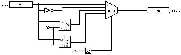
The following ALU has an 8-bit input (arg0) a 2-bit input (opcode), and an 8-bit output (result). A 4x8 multiplexer loads the output with one of four operations:
if (opcode == 0)
result = arg0;
else if (opcode == 1)
result = ~arg0;
else if (opcode == 2)
result = arg0 << 1;
else
result = arg0 >>> 1;
Here's the circuit:
The actual circuit can be found in alu2.circ.
IR
Create a 6-bit instruction register (IR). The output, Q, of the IR should be connected to a splitter with a fan out of 3. The upper 2 bits will connect to the opcode of the alu. The lower 2 bits will select the source register, and the middle 2 bits will select the destination register.
Registers and Bus
Create 4 8-bit registers: R0, R1, R2, and R3. The output pin, Q, of each register should connect to the input pin of an 8x4 multiplexer. The output of this multiplexer should connect to arg0 of the alu. The lower 2 bits of IR should connect to the select/control bits of the multiplexer.
Use a bus architecture to connect the result pin of the alu to the data pin, D, of each register.
Use a 1 x 4 de-multiplexer to connect a clock to the clock input of each register.
Connect the middle 2 bits of the IR to the control pin of the de-multiplexer.
Testing
Test by entering values for IR, R0, R1, R2, and R3. Click on the clock input to move the data around the data path.
Question
How would you have to alter your design if aly had two data inputs: arg0 and arg1?