In the real-world, it has been observed that Ethernets tend to work best when they are lightly loaded.
Utilization over 30% is considered heavy on Ethernet -- too much traffic is wasted on collisions.
Since typically Ethernet have less than 200 hosts, and are far shorter than 2500m, both the round-trip
delay and the likelihood of collision are much smaller.
Ethernet is successful because it is reasonably easy to implement and administer. There is no hardware to maintain such as
switches, cable is cheap, and the only cost to adding an additional node is the cost of a network adaptor.
Nowadays, Ethernet can run up to 10Gbps and can support larger jumbo packets of up to 9000 bytes.
Rings
Ring networks, like Ethernets are shared-media networks.
Unlike Ethernets though, they deterministically share the network, so are interesting for that reason (which is why I
am talking about them for a couple of slides).
The grand-daddy of ring networks is IBM's Token Ring which was standardized as 802.5.
Another ring network is Fibre Distributed Data Interface (FDDI) token ring.
Neither of these is in common use; however, slightly more recently Resilient Packet Ring (RPR) (2011), standardized
as 802.17, has been proposed for MAN (metropolitan area networks) settings (again didn't catch on).
In a ring network each host is connected to two other machines such that the graph of all the machines
looks like a circle (that's why its called a ring).
Ring Operation In Brief
In a token ring, a special bit sequence circulates around the ring in a fixed direction.
Each host receives and then forwards this token.
When a node that a has a frame to transmit sees the token, it takes the token off the ring (does not propagate it).
It instead then sends the frame it wants to send.
As the packet flows around the ring each node looks to see if it is the recipient. If so, it sets an A bit in the frame header to 1. It
then copies the packet to its buffer and sets a C bit in the frame header to 1, but does not remove it from the ring.
When this frame makes it way around the loop and comes back to the sender, the sender takes it off the ring, and then
reinserts the token. Using the A bit it can determine if the receiver was present, using the C bit it can determine if the receiver's buffer was
empty enough to actually receive the data.
Token Ring made use of a parameter Token Holding Time to control how long a sender could hold the token and send consecutive frames.
FDDI tries to improve ring utilization by using a dual ring set-up. RPR didn't use a token but allowed nodes to start sending a frame whenever there
was no frame to forward. If a frame comes in while sending, it is supposed to be buffered and then sent.
Keeping Rings connected
So far we described the basics of how to transmit frames in a token ring.
Of course, this relied on machines being connected in a ring. What happens if one
machine fails?
If we do nothing, then it is no longer a ring and the token will fly off one end to oblivion, and no one will be able to talk.
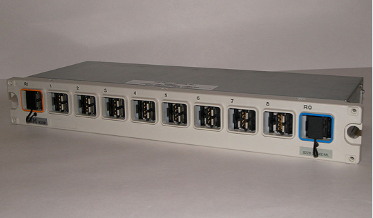
One solution is to connect each station to a electromechanical relay. If the station is healthy the relay stays open and the current goes through the given host. If the host dies and stops providing power to the relay, the relay closes, and the ring automatically bypasses the station. This only works for electrical cable, not fiber.
Typically, several relays are packed into a single box called a multistation access unit (MSAU).
A pair of connections (probably one cable but with an incoming/outgoing line) is then run from each host to this box.
It is also possible to chain boxes.
Quiz
Which of the following is true?
The CRC checks in Ethernet can correct up to three errors in a frame.
The receiver window size must be larger than the sender window size
in the sliding window protocol.
The MAC algorithm uses pseudo-random number generators.
Introduction to Wireless
We will now consider how the data link layer works in different wireless technologies.
We will consider Wi-fi, Bluetooth, and cellular.
These share some of the issues of wired networks like error detection, framing, and reliability.
They also have new issues not typical of wired networks: use of power (as devices tend to operate off battery), power of transmissions, interference, etc.
Media control is also much more important for wireless as it is difficult to direct radio transmissions to a single receiver.
Often wireless networks are categorized by the data rates they provide, how far apart the communicating nodes can be, and what portion of the EM Spectrum them use (bandwidth).
More Wireless Considerations
Wireless signals weaken (attenuate) as `1/r^2`. The coverage of a signal is thus based on the power of the broadcast and this.
In the United States, the Federal Communications Commission regulates what frequencies ranges and at what powers different operators can have. Some frequencies (AM/FM/TV) are required to have a licence, some are licensed exempt.
We have previously mentioned spread spectrum techniques to share some frequencies.
We distinguished different levels of mobility for the client. Almost zero: which might happen with
a very directional base station such as in the early versions of WiMax. Mobility within the range of a base station:
Bluetooth. Mobility between base stations: Cell phones and to a lesser degree Wi-Fi.
One interesting aspect of wireless is that it naturally supports point to multi-point communication.
It is also possible for wireless networks to be set-up in a mesh or ad-hoc fashion where there is no centralized base station.
From a power consumption point of view this might make sense if one had a lot of low-powered devices. Research in this area is
still in the early stages.
Wi-Fi
Wi-Fi is a trademark of the Wi-Fi alliance. This alliance certifies devices that meet the 802.11 spec.
Wi-Fi is designed for the limited geographical area, local area network setting (home, offices, etc).
Like Ethernet its main challenge is to mediate access to a shared media -- in this case, radio signals.
Over the next few slides, we will explore its functioning in more detail...
Physical Properties
802.11 can run over six (so far) physical layer protocols: five based on spread spectrum radio, and one
over diffused infrared.
The original 802.11 had two radio-based physical layer standards: one using frequency hopping among 79 1MHz channels,
and the other using direct-sequence with an 11 bit chipping sequence. Both ran at 2Mbps.
The original 802.11b used direct sequence spread spectrum and could run at 11Mbps.
802.11a came next. It offers speeds of up 54Mbps. However, it ran on the more line of sight frequency of 5Ghz.
It used a type of frequency division multiplexing known as orthogonal frequency division multiplexing (OFDM).
802.11g runs in the original frequency range and is backward compatible with 11b, but offers 54Mbps speeds.
The 802.11n also operates at the 2.4Ghz frequency and can be backward compatible (probably slows down higher speed clients). To transmit at higher speeds (150Mbps) requires more antennas and a technique called multiple input multiple output (MIMO) is used.
All of these used radio at the 2.4 GHz frequency range.
802.11ac uses a more advanced version of MIMO (MU-MIMO )and also operates at the higher frequency 5GHz band as well and can achieve rates of 450MBps.
The next standard is IEEE 802.11ax, however, for branding reasons is is called WiFi 6 (and previous standards are retcon branded WiFi 5,4,...). It incorporates orthogonal frequency-division multiple access (OFDMA), a cell-phone technology. It also supports operating at 6Ghz. It can operate theoretically at speed up to also 10Gbps.
WiFi 7 is expected by 2024. It should have theoretical speeds up to 46Gbps.
Collision Avoidance
One complication that a wireless system must solve that didn't need to be solved in the Ethernet setting is that different people might be able to receive signals from different people:
A
B
C
Orange here is suppose to represent the mix of the red and yellow radio signals. i.e., in the above both A and C can hear and send to B, but A and C are not in range of each other. A and C are called hidden nodes with respect to each other.
This can cause problems as a frame from A might collide with a frame from C at B, but neither A nor C is aware of the collision.
There is also the exposed node problem. It might occur in a situation like:
A B
C D
Suppose B is sending to A. C might think it cannot transmit because it can hear B. However, if would be okay to transmit to D, because D cannot hear B and A cannot hear C.
MACA
802.11 solves these problems by using multiple access with collision avoidance (MACA).
When the sender wants to send, it sends a request to send (RTS) control frame to the receiver. This frame has a field indicating how long it wants to hold the medium.
The receiver then sends back a clear to send (CTS) frame which contains the length field echo'd back to the sender.
Any node that sees the CTS frame knows it is close to the receiver, and therefore cannot transmit for that time period.
Any node that sees the RTS frame, but not the CTS frame, knows that it is out of range of the receiver so it is okay to transmit.
The receiver sends an ACK after successfully receiving the sender's frame.
If two senders' RTS's collide, then there won't be any acknowledgment CTS's. In this circumstance, the senders are supposed to wait a random amount of time and send again.
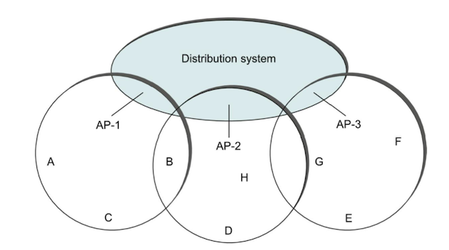
Distribution System
In 802.11 terminology, base stations are called access points.
Different base stations are connected to each other via a so-called distribution system. This might be
Ethernet, Token ring, etc. The distribution network runs at layer 2.
Each node associates itself with one access point. For example, node A might be associated with AP-1 and node E might be associated with access point AP-3.
If node A needs to communicate with node E, it is up to the distribution network to get the frame to the correct place. This might involve using a bridging algorithm like what we'll learn when we cover Ch 3.
To select an access point to associate itself with, a node uses the following scanning algorithm:
The node sends a Probe frame.
All APs within reach reply with a Probe Response frame.
The node selects one of these and sends an Association Request frame.
The given AP responds with a Association Response frame.
Another way, a node might associate itself with an access points relies on the fact that APs can also periodically send out Beacon frames which advertise the capabilities of the access point. A node can send an Association Request frame in response to join the access point, if it wants.
Frame Format
16
16
48
48
48
16
48
0-18496
32
Control
Duration
Addr1
Addr2
Addr3
SeqCtrl
Addr4
Payload
CRC
The control contains three important subfield a 6-bit Type field (RTS or CTS, etc); and two single bit fields ToDS and FromDS. These are use to indicate whether the frame had to be forwarded across the distribution system.
If both ToDS and FromDS are 0, then Addr2 identifies the source node and Addr1 identifies the receiving node. In the both non-zero case, Addr3 and Addr4 are used to denote the intermediate receiver and the intermediate source.
Bluetooth
Bluetooth (802.15) fills the niche of very short-range communication between mobiles phones, notebooks, and other peripherals.
Some example uses might be to pair a cell phone to a headset or to send photos or business cards from a cell phone to
a laptop. This size range of communication is often referred to as a Personal Area Network (PAN).
Bluetooth uses a licensed exempt 2.45GHz radio band and has a typical range of 10m and bandwidth of 1 to 3 Mbps.
Because its intended use only requires a limited range, power consumption is low.
The standardizing body for Bluetooth, the Bluetooth Special Interest Group, has specified an entire suite of protocols that Bluetooth can support in addition to just the link layer protocols. These are called profiles. For example, there is a protocol describing how to sync PDAs with a computer over Bluetooth. There is an object exchange protocol (OBEX). There is also a profile that gives mobile computer access to a wired LAN like 802.11.
The basic Bluetooth network (a piconet) consists of a master device which is paired with up to seven slaves. Slaves do not directly communicate. The spec also describes how the pairing based on a shared passkey is established.
To maximize the limited radio bandwidth that Bluetooth has, Bluetooth uses frequency spread spectrum techniques. It uses FDM amongst 79 channels, using each for 625 micro seconds at a time.
Synchronous time division multiplexing is also used; that is, time is divided into slots. Only the master can send on even numbered slots. A frame can take either 1, 3, or 5 consecutive slots.
In addition to seven active slaves; piconets are allowed up to 255 parked slaves, which are parked in a low-power consumption state and which can be woken up by the master.
Bluetooth also specifies how devices can be discovered. A device can make a request of any devices (set to discoverable) in range for information such as device name, device class, list of services, technical information.
Access Networks
In addition to Ethernet and WiFi connections we typically use to connect to the Internet at home, most people connect to the internet over an access or broadband service that we buy from an ISP.
We next briefly look at two common technologies used by these services: Passive Optical Networks (fiber-to-home) and Cellular networks.
Telephone and cable companies (Internet Service Providers) often operate a national backbone network. Connected to the periphery of this network are hundred or thousands of edge site, each of which services a city or neighborhood.
Edge sites are commonly called Central Offices in the telco world, and Head Ends in the cable world.
Passive Optical Networks
PON is the technology most commonly used to deliver fiber-based broadband to homes and businesses.
It uses a point to multi-point design, where a single point can fan out to up to 1024 homes.
These networks use splitters to passively forward signals upstream and downstream without storing frames
(like an optical version of Ethernet repeaters).
Framing occurs in the individual homes in a device called a Optical Network
Unit (ONU) and at the point source in a device called a Optical Line Terminal (OLT).
To connect the point to the ISPs backbone an Agg Switch aggregates traffic from a set of OLTs and a BNG (Broadband Network Gateway) meters Internet
traffic for the sake of billing.
For multi-acccess control, upstream and downstream traffic are transmitted on two
different optical wavelengths, so they are completely independent of each
other.
Downstream traffic starts at the OLT, and the signal is propagated down every link in the PON. So each frame reaches each ONU and an identifier is used by the ONU to determine if it should keep a frame or not. Encryption is used to prevent eavesdropping.
Upstream traffic is then time-division multiplexed on the upstream
wavelength, with each ONU periodically getting a turn to transmit.
Cell Technologies
Cell Phone technologies can also be used to get mobile computers to communicate.
The frequency bands for cell phones vary slightly for different places around the world. Typically and traditionally, it operates in the 700MHz to 2400 MHZ range. Newer 6GHz, and 24 GHz ranges are also opening up.
Another issue is that there are a fair number of incompatible cell phone standards and a variety of legacy protocols which are supported by different carriers to different extents.
Cell phones also rely on the use of base stations, often called Broadband Base Units (BBUs) (also known officially as Evolved Node B (eNodeB or eNB -- NodeB is what the radio unit used to called)).
Mobile devices that connect to a BBU are referred to a User Equipment (UE).
A set of BBUs are anchored at an Evolved Packed Core (EPC) hosted at a central office. The area served by an EPC is called a Radio Access Network or RAN.
The geographic area served by one station is called a cell.