Last Wednesday, we finished talking about different kind of physical links that could be used in our networks: leased links, last mile links, wireless
links.
We discussed different ways to encode bits on a physical channel: NRZ, NRZI, Manchester Encoding, 4B/5B, etc.
We then discussed different formats for writing frames to a channel: byte-oriented protocol, using either a sentinel (BISYNC and PPP) or byte counting (DDCMP), and bit-oriented protocols (HLDC)
We briefly started talking about clock-oriented framing... Let's begin today by reviewing that...
SONET and Clock-based Framing
Synchronous Optical Networks (SONET) use a third approach to framing known as clock-based framing.
SONET was developed at Bell Communication Corporation, ANSI, and it has been adopted by the ITU-T.
SONET solves both the framing and encoding problem and it also supports multiplexing several low-speed links
onto higher speed links.
In SONET a frame is sent every 125μS whether or not one has data. Frames are sent based only on the clock so
are synchronous.
One kind of traffic we'll later consider over SONET is called ATM. ATM cells do not arrive based on a clock,
so the A in ATM stands for asynchronous.
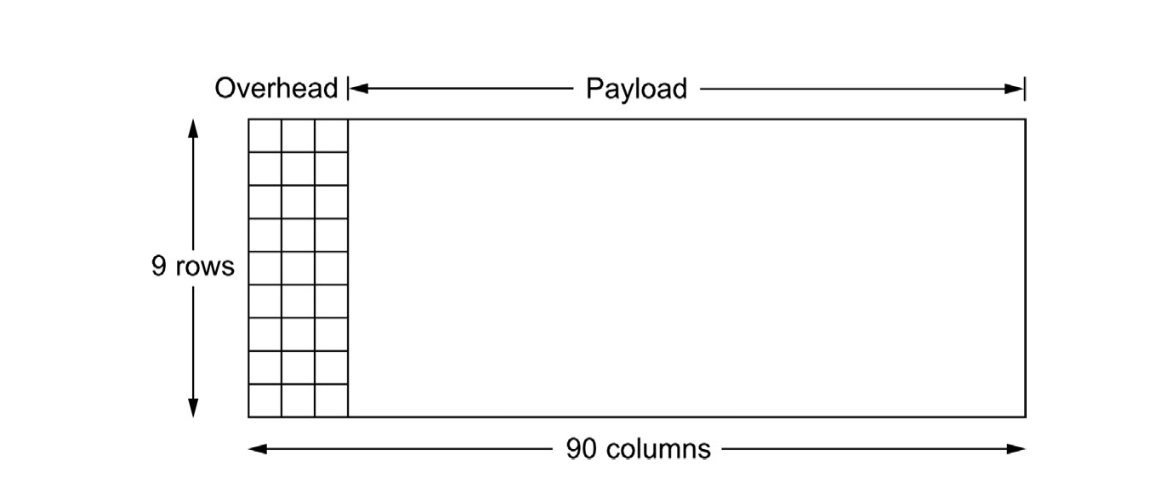
SONET STS-1 Frames
An STS-1 frame consists of 9 rows each of 90 bytes.
The first 3 bytes of each row are overhead, but the remaining "payload" bytes can be used for data.
The first three rows of overhead data are called the section overhead. Section overhead is checked at
the start of each section (frame).
As an example the first two bytes of each frame (first two overhead bytes of first row, i.e., section overhead)
contain a special bit pattern.
To sync itself with the sender, the receiver looks for this bit pattern repeating every 810 bytes.
The last six rows of overhead bytes are called line overhead. They are checked each line rather than each
frame.
More on SONET Frames
The overhead bytes are encoded using NRZ.
The payload bytes are encoded by XORing them against a fixed known 127 bit pattern that has plenty of 1's
and 0's in the hope of reducing the number of all 1 or all 0 stretches in the sent data.
In SONET, a frame is always 125μS for all STS-N. So an STS-N which is N higher transmission rate
can carry a payload which is N times bigger than an STS-1 frame.
An STS-N frame can be built out of N, STS-1 frames by interleaving the bytes of these frames. This results in an
even spacing in time for the bytes of a particular STS-1 sub-frame and allows the subframes to be de-multiplexed more easily.
I.e., the bytes of a particular STS-1 sub-frame (even if the bits in the byte arrive more quickly) still come at a steady 51.84 Mbps, the speed of STS-1.
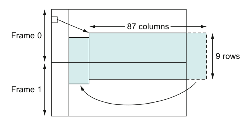
The payload of a frame need not be contained completely within the frame or start at the start of a frame.
This is useful because no matter what we have to send SONET frames every 125μS; however, an ATM cell might
arrive after we have begun sending a dummy SONET frame without useful data.
The line overhead bytes can be used to specify a synchronous payload envelope which is an offset to the starting
position of the payload within a frame (see image above). This payload could potentially cross frame boundaries.
This mechanism can be used also for concatenating frames to make an STS-N link look like a single channel rather than N multi-plexed ones. Call this mode of operation STS-Nc. I.e., STS-3c, etc.
Error Detection
So far we know different ways to encode 0 and 1 onto low and high signals, and
we know techniques to figure out when frames start and end.
One problem we still need to solve is how to handle bit errors in frames.
As we saw many of the frame formats of today either had checksums or CRCs
(cyclic redundancy checks). These are used to detect errors in frames.
There are two ways one could handle bit errors in frames: (1) One can use an error detecting code. Then if an error is detected one resends the frame. (2) One can use an error correcting code which provided not too many bits are messed up allows one to determine which bit to fix.
We look at three error detecting codes: two-dimensional parity (used by BISYNC), checksums, and CRC (used by HDLC, DDCMP, Ethernet, and Token rings).
Two Dimensional Parity
We will describe 2D PARITY in the context BISYNC, which used IBMs old 7-bit character encoding EBCDIC.
First, after every 7 bits we count the number of 1's we saw in those seven bits. If this was odd we output a 1; otherwise a 0.
For example, if we see 0101001, we would output a 1.
This last bit is called a parity bit.
Adding parities for each 7-bit sequence we want to send, would be called doing a 1D-parity check. This can detect any odd number of errors in the 7+1 bit sequence.
In BISYNC, after every sixth 7 (data) + 1 (parity) = 8 bit sequences, we send a parity row. We first imagine we have a 6 row by 8 column rectangle, and for each column calculate its parity and write it to that column of the parity row.
This is stronger than a 1D parity set-up in that we can detect any odd number of errors in either rows or columns. However, we now have 14 redundant bits for every 42 bits of data.
Internet Checksum Algorithm
This algorithm is used at the internet/network layer; whereas, the other two detection algorithms we will consider are at the data link layer.
As in practice most errors are caught in the data link layer the detection needed at this higher layer does not have to be as strong.
The checksum algorithm views data as a sequence of 16-bit integers.
The checksum maintains a sum of the integers seen in the frame as calculated using ones complement arithmetic and keeping only the lower order 16 bits.
Ones complement is one of three common ways to represent signed integers in binary. These are:
Sign and Magnitude Use the high order bit for the sign of the number, use the remaining bits for magnitude. So if working with 8-bit numbers
1100 0000 represents -64; whereas 0100 0000 represents 64. 1000 0000 represents -0 and 0000 0000 represents +0.
One's Complement High order bit still represents sign, but given x to make -x one inverts each of the bits. In this scheme for 8 bit numbers,
0100 0000 is still 64, but 1011 1111 is -64. To add two numbers in ones complement, you first add the two numbers using binary addition, if when adding
the high order bit you get a carry bit (a 9th bit), then you add one to the low order 8-bits. Notice adding 0100 0000 + 1011 1111 = 1111 1111 which represents -0.
As a 4 bit ones complement example: If we add -5 + -3 in 4-bit 1's complement, we first add the two numbers to get
a 5-bit number 10110 where the high order bit is the so called carry bit. We strip any carry
bit to get 0110, and if the carry bit was on we increment the result to get 0111, which is low order 4 bits of -8 (which is the way we'd keep things in a checksum).
Two's Complement. Used to solve the problem that in one's complement you can have two numbers representing 0. For example 0000 0000 and 1111 1111.
In two's complement, positive numbers are the same as in one's complement, but for negative numbers one increases the magnitude by 1. So 1011 1111 is -65 in
two's complement. Addition in two's complement is the same as addition of the numbers viewed as unsigned integers.
Cyclic Redundancy Check Codes
These are also known as polynomial codes.
A k-bit frame is viewed as specifying the coefficients of a degree k-1 polynomials.
For example 101 code 1x2 +1x0.
Polynomials can be added mod 2, they can also be multiplied and divided.
In a CRC code, both sender can receiver agree on on a generator polynomial G(x) which has both its high and low order coefficient 1.
We assume the message m has length > deg(G)=r.
Let M(x) be the polynomial of the message.
To compute a checksum for a message we (1) Compute xrM(x), (the bit sequence of this polynomial is that of M(x) shifted over r bits). (2) Divide xrM(x) by G(x) to get a remainder R(x). (3) Send the coefficients of T(x) = xrM(x)-R(x).
More on CRC codes.
Notice T(x) is divisible by G(x).
Suppose T(x)+E(x) arrives.
Then (T(x) +E(x))/G(x) = E(x)/G(x).
The only way an error is undetected is if this value is 0.
If there was a single bit error then E(x)=xi for some i which can't be divisible by G(x). So any single bit error will be detected.
If there are two errors then E(x)= xi+ xj where i>j. So E(x)= xj(xi-j +1). So this error will be detected provided that G(x) does not divide xk+1 for any k up to i-j.
There are some low degree polynomials that will give this protection to very long frames. For instance, x15+ x14+1 does not divide xk +1 for any k below 32768.
If E(X) contains an odd number of terms (hence errors), then it cannot have x+1 as a factor mod 2, so if x+1 is a factor of G(x) we can catch these errors.
To see this suppose E(x)=(x+1)Q(x) had an odd number of terms. Then E(1)=(1+1)Q(1) = 0 mod 2. On the other hand substituting 1 for an odd number of terms should give 1 mod 2.
CRC codes with r check bits will detect all burst errors of length ≤ r. Such an error would look like xi(xk +xk-1 + .. +x0). If G(x) has a x0 term, it will not have an xi factor, so if the degree of the parenthesized expression if less than G(x), the remainder won't be 0.
4B/5B encoding achieves a bit rate/baud rate of 80%
ifconfig can be used to find the route between two machines on the internet
Sentinel-based Framing techniques often make use of bit-stuffing.
Reliable Transmission
So at this point let's assume we can detect if there is an error in our frame.
How can the sender know if the frame arrived to the receiver correctly?
This is usually accomplished using two mechanisms: acknowledgments (ACKs) and timeouts.
The receiver can send a special control frame (a frame without data but whose header contains control information) ACKing the receipt of the data frame.
If the sender does not receive the ACK frame within a timeout period it retransmits the frame.
This strategy of using ACKs and timeouts is called ARQ (automatic repeat request).
We next look at several ARQ algorithms.
Stop and Wait
In the stop and wait protocol, the sender sends a frame, then waits for an acknowledgement of the frame
before transmitting the next frame. If the acknowledgment takes too long. Then the sender resends the frame.
There are four possible scenarios that could occur with this algorithm for a given frame:
The frame arrives okay and is acknowledged okay. This is the happy case.
The frame does not arrive okay. After the timeout period, the frame is re-sent and this time it is acknowledged. Even this is still pretty happy.
The frame arrives okay but the ACK frame is lost. The timeout then happens, the frame is re-sent and it is acknowledged
correctly. This situation might cause problems (similar to the item 4 below).
The frame arrives okay but the ACK frame is sent but it arrives to the sender after the timeout period. So the sender has
already re-sent the frame. This might be bad. How does the receiver know the re-sent frame is not the next frame?
To avoid the problem of situation 4, typically a 1-bit control sequence is used in the header of frames sent and in the acknowledgment
frame. Each time the Sender sends, it adds 1 to this sequence number mod 2. The receiver's ACK frame should say in its header the sequence
number being acknowledged.
The Drawback of Stop and Wait
The main problem with stop and wait is that it doesn't make efficient use of the bandwidth resources.
To see this suppose one had a 1.5Mbps link with a 45ms RTT.
Suppose the frame size is 1KB. Since only one frame can be sent per RTT, implies our effective bit
rate is (1024 * 8)/.045 = 182 Kbps -- only 1/8 of the total channel bandwidth.
We would like somehow to be able to send 8 frames before we have to send an acknowledgment.
Sliding Window -- the Sender
In the sliding window protocol, the sender assigns a sequence number SeqNum to each frame. For now we'll assume that this number could be any natural number
(even though it will eventually be implemented with some fixed number of bits).
The sender also has:
a sender window size (SWS) -- the maximum number of unacknowledged frames that the sender can transmit. We will choose
the SWS to try to keep the pipe as full as possible.
a last acknowledgment received (LAR) -- the sequence number of the last frame acknowledged.
a last frame sent (LFS) -- the sequence number of the last frame sent.
The sender maintains that LFS - LAR ≤ SWS.
The sender has a buffer of size SWS which could hold all of the frames which might not yet be acknowledged.
The sender has a timer for each frame that has not been acknowledged, and re-sends a frame if its timer goes off.
An acknowledgment from the receiver of a sequence number will now be a promise from the receiver that all smaller
sequence numbers have been received. So when the sender gets an acknowledgement it checks if the number is between
LAR and LFS, if it is, it sets LAR to this number -- all of the frames less than this are viewed as acknowledged.
Sliding Window -- the Receiver
Meanwhile, the receiver also maintains three variables:
a receive window size (RWS) -- maximum number of out of order frame the receiver is willing to receive.
a largest acceptable frame (LAF) -- the highest sequence number that the receiver is currently willing to accept.
a last frame received (LFR) -- the sequence number of last frame received.
The receiver maintains that LAF - LFR ≤ RWS.
When a frame with SeqNum arrives, the receiver checks if SeqNum ≤ LFR or SeqNum ≥ LAF. If so the frame is out of the
receiver's window and is discarded.
If the frame is in the receiver window, it is accepted.
The receiver ACKs the frame with sequence number SeqNumToAck, which denotes the largest sequence number not yet
acknowledged, such that all frames less than or equal to it have been received.
The receiver then sets LFR =SeqNumToAck and LAF = LFR + RWS.