Finite State Machines
A finite state machine (fsm) diagram, also called a statechart diagram, is a directed graph. The nodes represent internal states of some abstract machine. The arrows represent state transitions. A state transition is usually triggered by some event, such as receiving a signal, or timing out. At any given moment of time only one state in an FSM is considered to be the active state. One state is usually designated as the start state. Zero or more states may be designated as final or accept states.
Here's a simple process model:
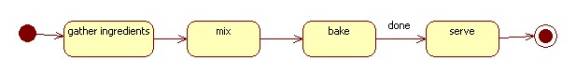
In this diagram states represent actions.
Note the start and final states.
The "done" label is a timing event.
An unlabeled transition is triggered by the completion of the source action state.
Transitions
A transition is enabled if its source state is active and if any additional enabling condition is true. Only an enabled transition can be executed. Executing a transition changes the active state from the source state of the transition to its destination state. In addition, some actions may be performed.
The (optional) label of a transition arrow has the form:
trigger[guard]/effect
where
trigger = the event causing the transition to execute
guard = an additional enabling condition
effect = actions performed by executing the transition
Trigger events can be:
signal events
call events
timing events
change events
For example:
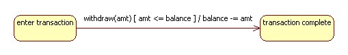
Examples
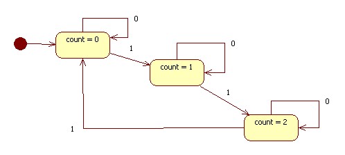
Lifecycle: Sequential Circuits
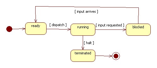
Lifecycle: Process
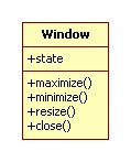
Lifecycle: Window
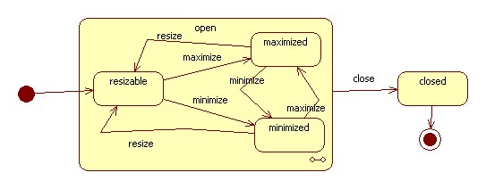
Note that "open" is a macro state containing micro states.
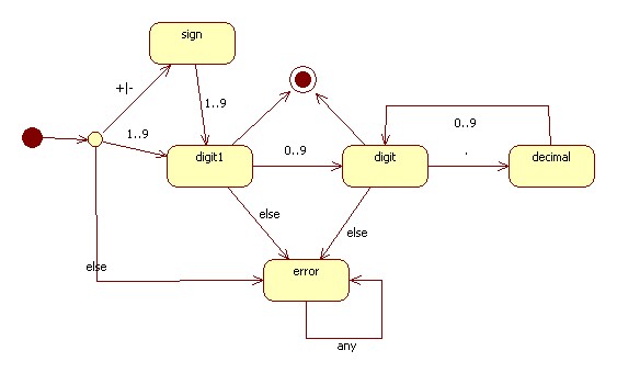
Process: Token Recognizers (a.k.a. scanners)
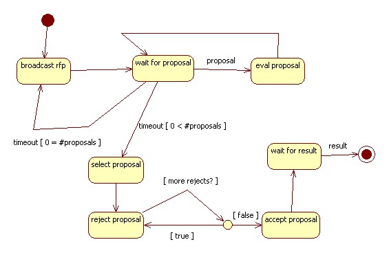
Protocol: Contract Net Protocol
Behavior of an agent in the initiator role of the Contract net Protocol: