Control Flow in
Jedi 1.0
Executing an
expression
Assume the user enters the following:
-> def x = 3
OK
-> x + 2
The following UML sequence diagram shows the flow of control through the Jedi 1 interpreter:
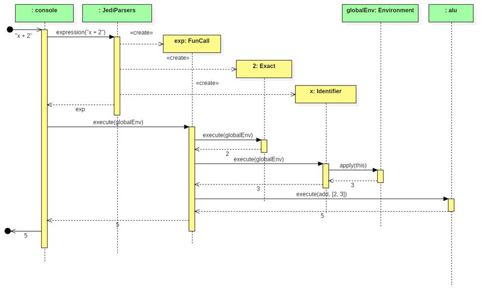
Notes:
· Sequence diagrams are used to show how a group of objects collaborate with each other.
· Rectangles at the top of a sequence diagram represent the collaborating objects.
· The dashed vertical lines are called lifelines. They represent the object's lifetime. Time flows downward.
· Solid arrows represent method calls.
· Dashed arrows represent the values returned by a method call.
· The yellow boxes along the lifelines represent the execution time of a method.
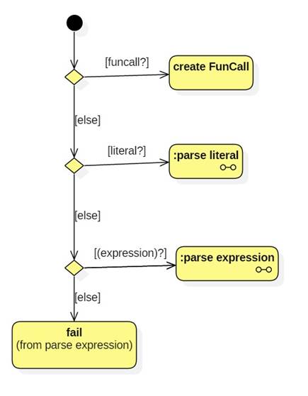
Parsing
Recall that the first parser parsed expressions:
def expression: Parser[Expression] = declaration | conditional | disjunction | failure("Invalid expression")
We can represent this using a UML activity diagram:
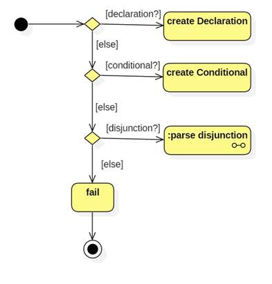
Notes:
· An activity diagram is similar to a flowchart. Yellow bubbles represent actions. Arrows represent the flow of control from one action to the next.
· Diamonds represent decision points.
· Labels on arrows (in braces) represent guard conditions. These must be true to allow control to flow down the arrow.
· Actions with the little dumbbell symbol represent sub-activities. These contain their own activity diagrams.
· The diagrams I present are a simplification of the flow of control through the parser.
parse disjunction
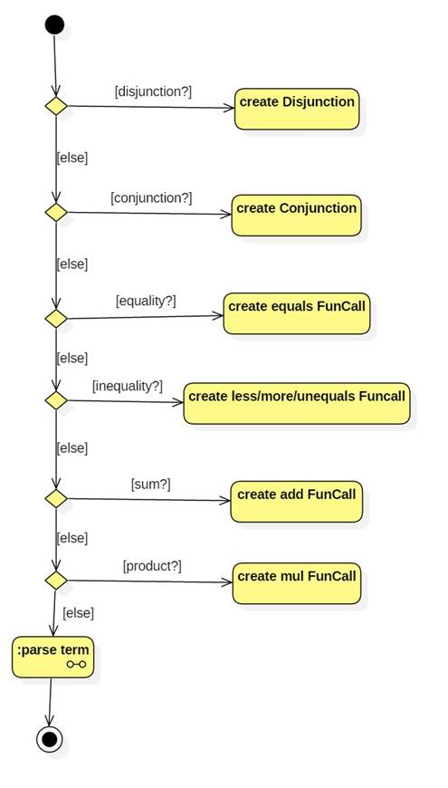
parse term
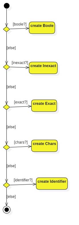
parse
literal