Overview of
Object-Oriented Analysis
Concepts
Models and
Activities
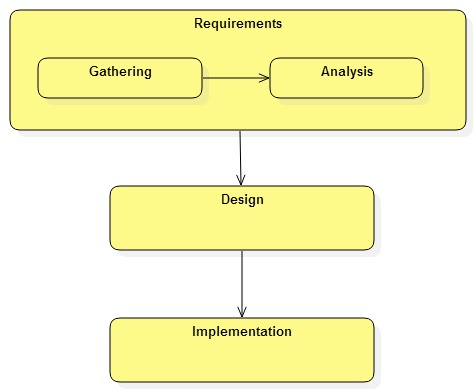
The requirements activity of software development is often divided into two sub-activities:
Notes:
· The output of requirements gathering is the requirements model. It documents all of the system's use cases.
· The requirements model is the input to the analysis activity.
· The output of analysis is the domain model.
· The domain model represents the important domain-specific concepts and relationships that are needed to understand and implement the requirements.
· Analysis and gathering often happen in parallel.
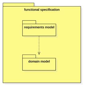
Together the domain and requirements models provide a model of the system from the user's perspective.
Both models (sometimes collectively referred to as the functional specification) are the input to the design activity.
The Unified
Modeling Language (UML)
· UML is a language for describing system models.
· UML models often include one or more views or diagrams. (Often the distinction between model and view gets blurred, but one model may have many views.)
· UML is standardized by the Object Management Group (OMG).
· Developers use computer aided software engineering (CASE) tools such as StarUML 2 to create models.
· The requirements model includes one or more UML use case diagrams.
· The domain model includes one or more UML class diagrams.
Actors, Use Cases,
and Scenarios
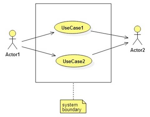
· Actors are users or systems external to the system being developed. The system interacts with its actors.
· A use case is a system function or goal. Use cases are often associated with specific actors.
· A use case scenario details the interaction between a use case and its associated actors.
Here is the notation used in a UML use case diagram:
Classes and their
Relationships
A class model/diagram contains classes, interfaces, and relationships between them.
These relationships include associations, generalizations, and realizations.
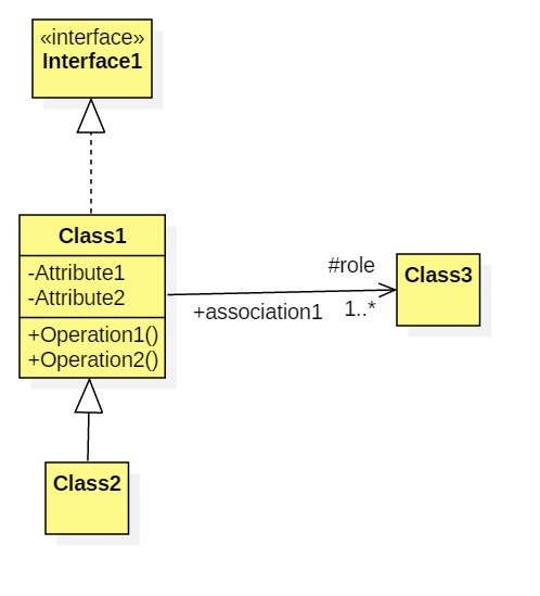
Instances of classes are objects. Instances of associations are links.
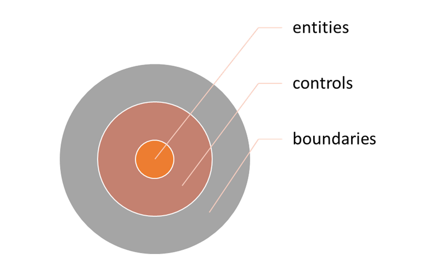
Entities, Controls,
and Boundaries (The Hexagonal Architecture)
The analysis model consists of entity, control, and boundary classes usually arranged in concentric layers:
UML has pre-defined icons for these types of classes:
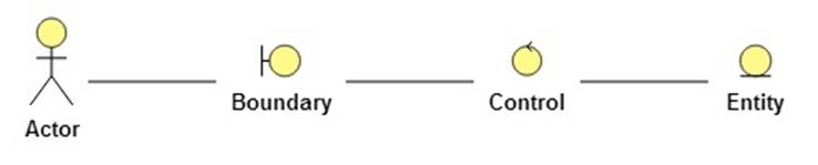
Entity classes represent application domain concepts such as Employee, Transaction, Process, Money, Measurement, etc.
Boundary classes are actor interfaces: user interfaces, gateways, proxies, etc.
Control classes often correspond to use cases. They coordinate the use case scenarios by interacting with boundaries and entities.
The Layered
Architecture
The classes in a design model (the output of the design phase) can often be arranged in a hierarchy, with higher layers depending on lower layers, but not vice versa.
|
Presentation Layer |
|
Control Layer |
|
Domain Layer |
|
Infrastructure Layer |
· Presentation layer objects communicate with primary actors (users, clients, etc.). Examples include views, control panels, consoles, services, and APIs
· Control layer objects, called controls) orchestrate the use cases. (By implementing the scenarios.)
· Domain layer objects include entities (references) and values. (See above.)
· Infrastructure layer objects provide services to the higher layers such as storage, lifecycle management, communication, discovery, etc.
· Lower layer objects are more reusable than upper layer objects.
Special UML notation:
Domain Modeling
Domain model classes and associations represent
domain-significant concepts and relationships.
Examples of domains
·
Health Care (medical records, billing,
observations, treatments, etc.)
·
Insurance (risks, policies, claims)
·
Human Resources (employees, positions, shifts,
actions, etc.)
·
Fulfillment (eStore,
inventory, shipping, billing)
·
Engineering (process, system, design,
requirement, etc.)
·
Gaming (avatar, weapon, agent, maze, etc.)
Domain model
classes include references and values.
·
Instances of reference classes (aka references
or entities) refer to elements in the domain (person, event, transaction,
account, etc.)
·
Instances of value classes (aka values)
represent quantities (price, weight, temperature, size, date, etc.) and
qualities (color, shape, genre, rating, etc.)
·
Two reference objects are equal if they
represent the same element in the domain. (person1 == person2 if same dude!)
·
Two value objects are equal if they have the
same attributes. (price1 == price2 if price1.amt == price2.amt)
·
Duplicating value objects is no problem.
Duplicating references can lead to inconsistencies.
·
An aggregate is a collection of reference and
value objects that
·
Some domain elements are represented by
aggregates of reference and value objects. (customer =
person + address + credit card + etc.)
Domain Model
Associations
·
Domain model associations represent domain-significant
relationships (spouse-of, supervisor-of, subsidiary-of, friend-of, patient-of,
supplier-of, etc.)
Domain-Driven
Design
Domain-Driven design is a software development practice that maintains that the domain model from the analysis phase should evolve into the domain layer of the design model rather than be abandoned as an artifact of the analysis phase.
This means the domain layer specifies an implementation and faithfully models the domain.
Analysis Patterns
Analysis patterns are reusable fragments of domain models.
Example:
A Simple Account Management System