Requirements Overview
The requirements phase is often divided into two sub-phases:

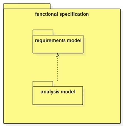
The output of requirements gathering is a requirements
model. This is the input of the analysis phase.
The output of requirements analysis is the analysis model.
The purpose of the analysis model is to help developers
understand the terminology and logic behind the use cases.
Together the analysis and requirements models provide a
model of the system from the user's perspective.
Both models (sometimes collectively referred to as the
functional specification) are the input to the design activity.
The Unified Modeling Language (UML)
UML is a language for building object-oriented models of
systems. A UML model often provides one or more views or diagrams. (Often the
distinction between model and view gets blurred, but one model may have many
views, and the models is principally a logical rather than graphical structure.)
UML is standardized by the Object
Management Group (OMG).
Developers use computer aided software engineering (CASE)
tools such as StarUML 2
to create models.
The requirements model includes one or more UML use case
models/diagrams.
The analysis model includes one or more UML class models/diagrams.
Both models may also contain behavior models of workflows, interactions,
and lifecycles.
Actors, Use Cases, and Scenarios
Actors are users or systems external to the system being
developed. The system interacts with its actors.
A use case is a system function or goal. Use cases are often
associated with specific actors.
A use case scenario details the interaction between a use
case and its associated actors.
Here is the notation used in a UML use case diagram:

Entities, Controls, and Boundaries
The analysis model consists of entity, control, and boundary
classes usually arranged in concentric layers:

UML has pre-defined icons for these types of classes:

Entity classes represent application domain concepts such as Employee, Transaction, Process, Money, Measurement, etc.
Boundary classes are actor interfaces: GUI, CUI, DAO, etc.
Control classes often correspond to use cases. They coordinate the use case scenarios by interacting with boundaries and entities.
Entity Layer = Domain Model = Analysis Model
A domain model represents the concepts and
relationships in an application domain.
The term "entities" is misleading. The entities layer is actually the domain model.
Boundary and control objects usually aren't elaborated in the analysis model. Therefore we use the terms domain model, analysis model, and entities layer interchangeably.
Example:
A Simple Account Management System