UML class diagrams as a conceptual models
A conceptual model captures the important concepts and relationships in some domain.
Concepts are represented by classes, while relationships are represented by associations.
Packages represent groups of related classes and associations.
Objects represent specific instances of classes.
For example a business might organize its concepts and relationships into three packages:
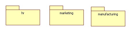
Classes
In the hr package we might find the Position and Person classes. Typical attributes of persons and positions can be listed in the attribute compartments of the respective class icons. Typical operations performed by persons and positions can be listed in their operation compartments:
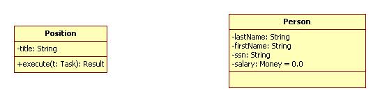
In this example, an object representing a position, vice president for example, has a title attribute of type String and an execute operation that takes a task, t, as an input, and outputs a result.
An object representing a person has four attributes: last name, first name, and Social Security number, all of type String, and a salary of type Money and with initial value $0.0. The person class has no operations specified at this point.
It is often the case that operations correspond to responsibilities and are not assigned to classes until the design phase. For this reason operation compartments are often suppressed in domain models. Attribute compartments can also be suppressed if they are not needed.
Note that the "-" sign indicates that the scope of an attribute or association endpoint is private, visible only inside of the class. Other possible scopes are:
+ = public = system-wide scope
~ = package scope
# = protected = subclass scope
Generally speaking, the default for an attribute or association endpoint is private, while the default for an operation is public.
Associations
The relationship "Position X is filled by person Y" can be represented by an association connecting Position and Person:
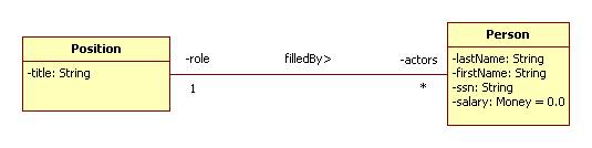
Note that the name of an association can be decorated by a tiny arrow showing which way the association is read. This helps distinguish a relationship from its inverse.
Note that the endpoints of an association can be decorated by:
name = the name used by objects on one end to refer to objects on the other end. For example, an employee refers to his position as his "role" while a position refers to the employees filling it as its "actors."
multiplicity = the number of objects that can be related to a given object. For example, a given position, vice president, say, can be filled by by 0 or more persons (indicated by "*"), while a given person, Joe Smith, say, can fill one position.
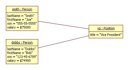
Objects
Specific persons and positions can be represented using objects. Specific instances of the filledBy relationship can be represented by links connecting the participating objects:
Abox versus Tbox
UML is only one of many languages for modeling domains. For
example, we can simply write down all of the facts about a domain using
formulas. This is essentially what
A collection of formulas describing a domain is called a knowledge base or ontology.
Ontologies are often divided into two parts: Abox and Tbox.
The Tbox is the terminology component of a domain model. It defines the vocabulary of the domain.
The Abox is the assertion component of a domain model. It collects together specific facts about the domain.
For example, compare the statements:
S1: A student is a person who is currently enrolled in a school.
S2: Ted Williams is a student at
S3: Bill Ding is a student at
S1 is a TBox statement, while S2 and S3 are Abox statements.
The Abox component must be compliant with the Tbox component. In other words, no Abox statement should use vocabulary not defined in the Tbox, nor should it use Tbox terminology in a way that is inconsistent with the constraints placed on these terms by the Tbox.
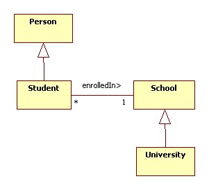
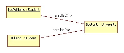
In a UML domain model, TBox statements are usually captured by a class diagram containing only classes, associations, and generalizations. Abox statements are usually captured by an object diagram. An object diagram is a class diagram containing objects and the links between them.
For example, here is the Tbox component of the educational domain:
Here is the Abox component:
Domains, Sub-domains, and Domain Dependencies
A domain model can be divided into models of sub-domains.
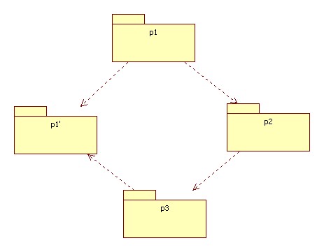
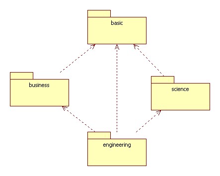
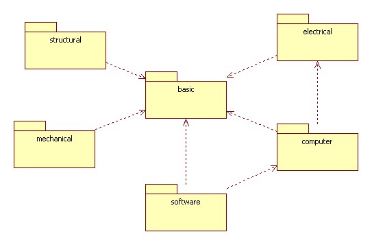
This can be shown by a package diagram. Recall that a package is a named collection of classes, objects, and sub-packages. A package diagram is a class diagram that shows packages and the dependencies between them. A dependency between two packages is represented by a dashed arrow. More specifically, dashed arrow from package A to package B indicates that package A uses some of the items contained in package B. We say that A imports from B or that B exports to A.
Here are a few examples:
A Design Principle
Avoid cycles in a package diagram. This can lead to cyclical dependencies that can be hard to resolve during the implementation phase.
Often cycles in the package diagram can be resolved by picking a package in the cycle and factoring it into two packages, one containing the components that are causing the cycle. For example, the following diagram contains a cycle:
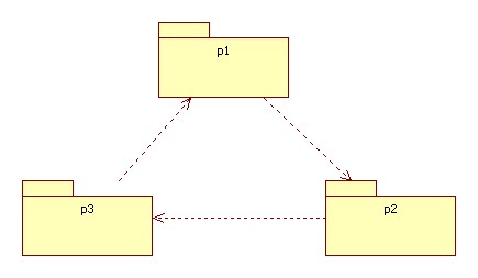
This can be resolved by factoring the elements in p1 used by p3 into a package p1':