UML in Prolog
Relationships can be viewed as directed graphs.
UML diagrams are directed graphs in which nodes represent classes or interfaces and arrows represent implementations, extensions, or associations.
Problem 1
Here's a fragment of an old class diagram for Jedi 1.0 from back in the days when Java was the meta-language:
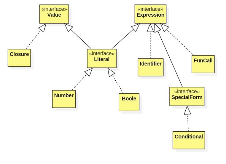
Represent this diagram as a Prolog knowledge base consisting of five predicates:
class/1
interface/1
extends/2
implements/2
depends/2
Note depends(A, B) it there is a chain of 0 or more arrows leading from A to B.
Problem 2
Here's another diagram from this model:

Represent this as a predicate:
consequent/2
alternative/2
condition/1