Creating UML Diagrams with MS Visio
Background
A package is a named collection of related elements.
Elements include UML diagrams plus all of the elements found in UML diagrams: classes, interfaces, objects, use cases, dependencies, statechart machines, etc.
A package is an element; therefore a package can contain sub-packages.
Package p1 depends on package p2 if some of the elements in p1 depend on some of the elements in p2. Here's the UML notation:
We also say that p1 imports elements from p2 or that p2 exports elements to p1.
Tip: try to avoid circular dependencies among packages.
Tip: package names conventionally begin with lowercase letters.
Create a new VISIO UML software system
Let's create a hypothetical system that controls access to secure areas.
From the File menu select: FILE/NEW/SOFTWARE/UML MODEL DIAGRAM
By default VISIO creates a top level system consisting of five packages: one static model package and four packages containing data types.
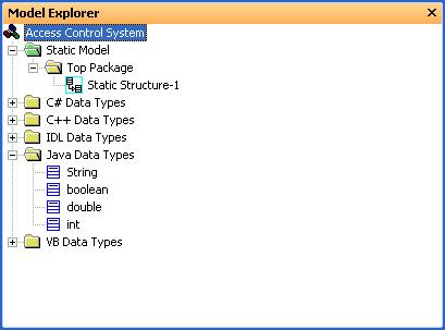
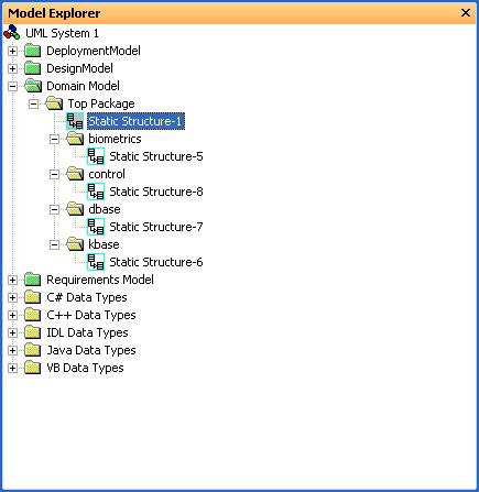
Here's a snapshot of the all-important Model Explorer window:
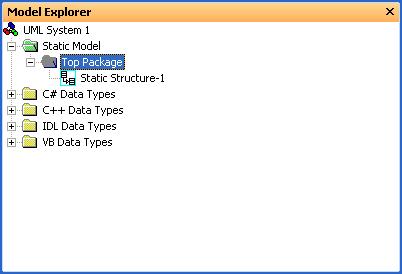
Notice that a model package by default comes equipped with a "Top Package" containing a blank class diagram.
VISIO calls class diagrams "Static Structure Diagrams".
Right clicking on any element in the model explorer brings up a short cut menu with appropriate operations for the type of element.
The last item on each shortcut menu is "Properties ..." This displays the properties dialog for the type of element clicked. We can use this to add and modify properties of the element.
Rename the System node "Access Control System".
Note: To delete an element from the system, select the element in the Model Explorer, then press the Delete key while holding down the Ctrl key.
Tip: Save your work frequently!
Adding Data Types
VISIO distinguishes between several types of packages:
A model package (green) contains only a single top level package.
A type package (yellow) only contains data types and interfaces.
A UML package (also yellow) contains data types, interfaces, classes, actors, use cases, subsystem packages, UML packages (i.e., sub-packages), and any type of UML diagram.
A subsystem package (red) seems the same as a UML package exceept for its color.
The top level system node can be thought of as a system package that only contains model and type packages.
True to MS form, VISIO doesn't come equipped with Java data types. We will need to add these ourselves:
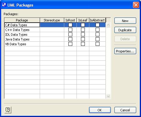
In the Model Explorer Window right click on the Access Control System root node and select "Packages ..."
In the UML Packages dialog create a new package called "Java Data Types":
Right click on the newly create Java Data Types node and select new/data type.
In the UML Data type Properties dialog name the type "int".
Repeat for double, boolean, and String.
Note that String isn't a data type, its a class. To recreate a large portion of the Java class library would be a major undertaking.
Adding Models
There are different schools of thought on what models or views of a system need to be built. We will take a simplified approach and create the following types of models:
Requirements Model
Domain Model
Design Model
Deployment Model
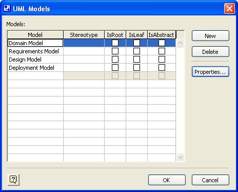
Begin by renaming "Static Model" "Domain Model", then select "Model..." from the system node's shortcut menu to get the UML Models dialog:
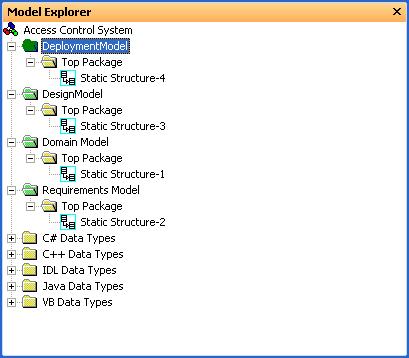
Here's a screen shot of the Model Explorer at this point:
Adding Packages to Models
The easiest way to add UML sub-packages to a UML package or Sub-system package is to drag packages into the parent package's static structure diagram. We can also connect the packages with dependency arrows.
Create the following diagram in the static structure diagram of the top package of the domain model:
Note that package names conventionally begin with lower case letters.
Here's a breakdown of the packages:
control: elements dealing with entering and exiting secure areas (guard, area, weapon, etc.)
kbase: elements dealing with knowledge base systems (rule, proposition, inference engine, etc.)
dbase: elements dealing with a database system (record, table, query, etc.)
biometric: elements dealing with biometrics (fingerprint, fingerprint reader, retinal scanner, etc.)
Obviously for a guard in the control package to determine if a person should have access to a secure area, the guard will need elements in the other three packages.
Here's a screen shot of the Model Explorer window:
Adding Classes to a Package
Drag a class icon into the Static Structure diagram for the control package.
We can right click on elements in a diagram to get a shortcut menu for this type of element.
The last item on the shortcut menu is the properties dialog.
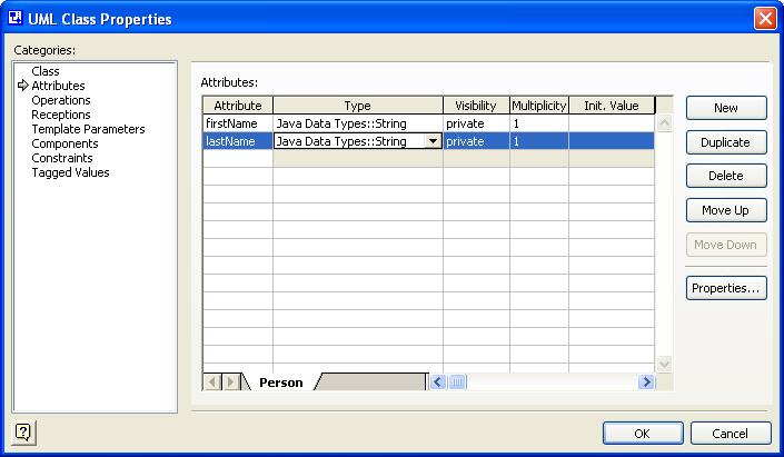
Use the properties dialog for the class icon to change the name of the class to "Person".
Use the properties dialog for the class icon to add first and last name attributes of type Java String.
Here's a screenshot of the UML Class Properties dialog:
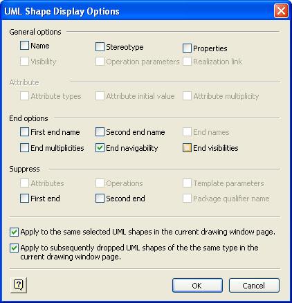
Select "Shape Display Options" from the class icon's shortcut menu to display the shape options dialog box:
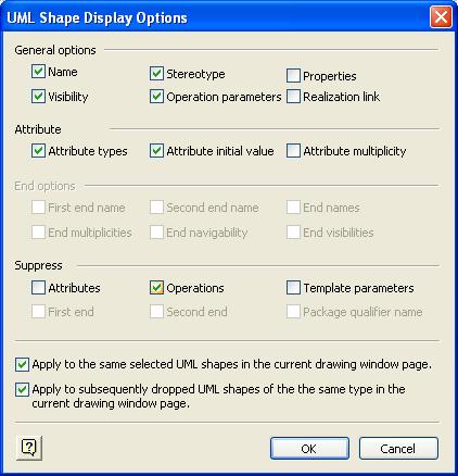
Check the Supress Operations box to hide the operations compartment.
Here's a screenshot of the class icon:
Adding an Association
An association represents a relationship.
For example, the relationship:
Person X is married to Person Y
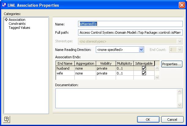
is modeled by an association named "isMarriedTo" connecting the Person class to itself:
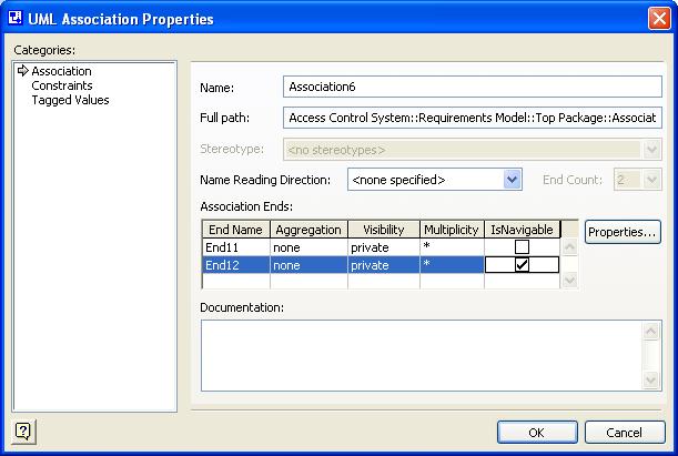
Here's a screenshot of the properties dialog for the association showing how endpoint attributes are specified:
Adding Objects to a Package
Static structure diagrams can contain packages, interfaces, classes, objects, and dependency arrows. But it's not a good idea to mix these together.
A static structure diagram containing only packages and dependency arrows is called a package diagram.
A static structure diagram containing only classes, interfaces, and dependency arrows (associations, generalizations, realizations) is called a class diagram.
A static structure diagram containing only objects and dependency arrows (links) is called an object diagram.
A class diagram usually models domain terminology (and in AI is called a T-box diagram).
An object diagram models specific assertions about a specific domain (and in AI is called an A-box diagram).
Here's an object diagram representing the assertion:
Bill Smith is married to Betty Smith.
To create this diagram:
Add a new static structure diagram to the domain model.
Drag two object icons into the diagram.
Use their property sheets to specify their names, class (Person), and attribute values:
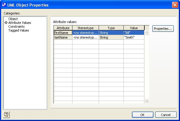
Note that having specified that smith1 and smith2 were instances of the Person class, Visio already knows the attributes, only the values are required.
Connect the two objects with a link.
Just as objects are instances of classes, links are instances of associations.
In the link dialog specify that it is an instance of the isMarriedTo association:
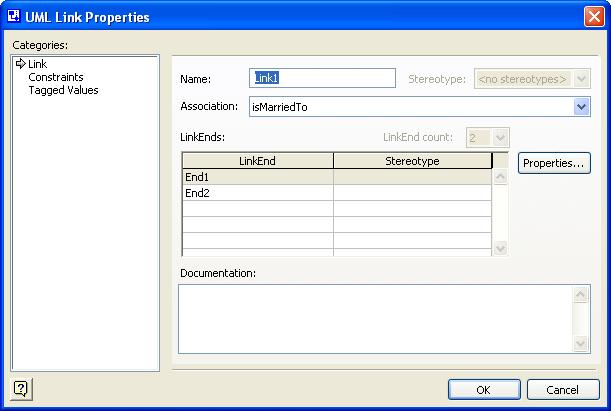
Automatically Visio supplies the endpoint names and navigability to the link.
Adding Use Cases to a Package
Delete the static structure diagram from the requirements model. Instead, add a use case diagram.
We are going to create the following use case diagram:
Begin by dragging use cases, actors, and system boundary into the diagram.
The arrows are called "communicates" in Visio. They are more commonly called actor associations.
After dragging the first arrow into the diagram select the shape display options from the arrow's shortcut menu.
Actor associations usually don't have names on their endpoints, nor do they have multiplicities, although navigability is useful to distinguish between primary actors (instigators) and secondary actors (responders). Turn off the end options and apply this to future actor associations:
To specify navigability (arrowheads) use the association's property dialog: