Designing Sequential Circuits
A Mod-2N counter is a sequential circuit with two inputs: x and clock, and an N bit output called state, which is the same as the internal state.
Internally, there are 2N states: 0, 1, 2, ..., 2N – 1
State changes occur on clock pulses according to the formulas:
if (x == 0) state = (state - 1) % 2N
if (x == 1) state = (state + 1) % 2N
Counters are useful as clocks that take as input a clock that divides time into two phases: 0 and 1, and splits this time into 2N phases.
For example, the fetch-execute cycle of a processor may need three phases:
phase 0: IR = cell[PC]
phase 1: PC++
phase 2: execute IR
Each of these phases might be divided into sub-phases.
Building a clocked Mod-4 Counter
In this section we will outline the technique for building a sequential circuit.
Step 1: Derive a state diagram and/or state table
A Mod-4 counter has 4 states:
00, 01, 10, 11
The output of a mod-4 counter is its state.
A mod-4 counter has a 1 bit input, x = 0 or x = 1 and a clock. On a clock pulse the state updates according to the formulas:
if (x == 1) state = (state + 1) % 4
if (x == 0) state = (state - 1) % 4
Here's a state diagram for a Mod-4 counter:
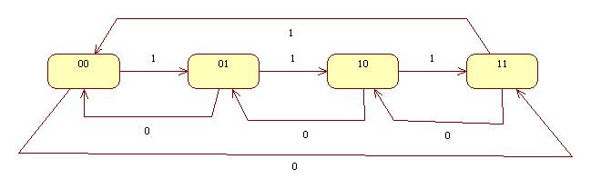
Here's the state table for a mod-4 counter:
|
current state |
x = 0 |
x = 1 |
|
00 |
11 |
01 |
|
01 |
00 |
10 |
|
10 |
01 |
11 |
|
11 |
10 |
00 |
Step 2: Compute p, the number and types of flip-flops needed
If the number of states is n, then:
2p-1 < n <= 2p
In out case n = 4 so we will need two S-R flip-flops: F0 and F1.
Call the outputs of F0 Q0 and Q0'. Call the outputs of F1 Q1 and Q1'. Then the state of our circuit will be Q1Q0.
Step 3: Separate the state transition table into p tables, one for each flip-flop
F0
|
current state |
x = 0 |
x = 1 |
|
00 |
1 |
1 |
|
01 |
0 |
0 |
|
10 |
1 |
1 |
|
11 |
0 |
0 |
F1
|
current state |
x = 0 |
x = 1 |
|
00 |
1 |
0 |
|
01 |
0 |
1 |
|
10 |
0 |
1 |
|
11 |
1 |
0 |
Step 4: Derive an input table for each flip-flop
F0
F0 has two inputs: S0 and R0.
|
current state (Q1Q0) |
x = 0 |
x = 1 |
|
00 |
S0 = 1, R0 = 0 |
S0 = 1, R0 = 0 |
|
01 |
S0 = 0, R0 = 1 |
S0 = 0, R0 = 1 |
|
10 |
S0 = 1, R0 = 0 |
S0 = 1, R0 = 0 |
|
11 |
S0 = 0, R0 = 1 |
S0 = 0, R0 = 1 |
F1
F1 has two inputs S1 and R1.
|
current state |
x = 0 |
x = 1 |
|
00 |
S1 = 1, R1 = 0 |
S1 = 0, R1 = 0 |
|
01 |
S1 = 0, R1 = 1 |
S1 = 1, R1 = 0 |
|
10 |
S1 = 0, R1 = 1 |
S1 = 1, R1 = 0 |
|
11 |
S1 = 1, R1 = 0 |
S1 = 0, R1 = 1 |
Step 5: Derive an input equation for each flip-flop and the circuit output equations
F0
S0 = !Q0
R0 = Q0
F1
S1 = !x && !Q0 && !Q1 || x && Q0
&& !Q1 || x && !Q0 && Q1 || !x && Q0 &&
Q1
= !(x || Q0 || Q1) || x && (Q0
xor Q1) || !x && Q0 && Q1
R1 = !x && (Q0 xor Q1) || x && Q0 && Q1
Step 6: Draw the circuit diagram
See mod4.circ
An Application: A four phase clock
Connect a 2-phase clock to the clock input of a mod4 counter and a constant 1 to x. Connect the output to the input of a 2-bit decoder.
Connect the 4 outputs of the decoder to LEDs (from the I/O library.)
Select "Ticks Enabled" from the Simulate menu.