Pattern Recognizers
A pattern is a binary string.
A pattern recognizer is a device with a 1 bit input, x, and a 1 bit output, found.
Found = 1 every time the pattern is entered, 1 bit at a time, through x.
A pattern recognizer must remember if some prefix of the pattern has been entered.
The following state diagram is a pattern recognizer for strings of the form: (111+0)+
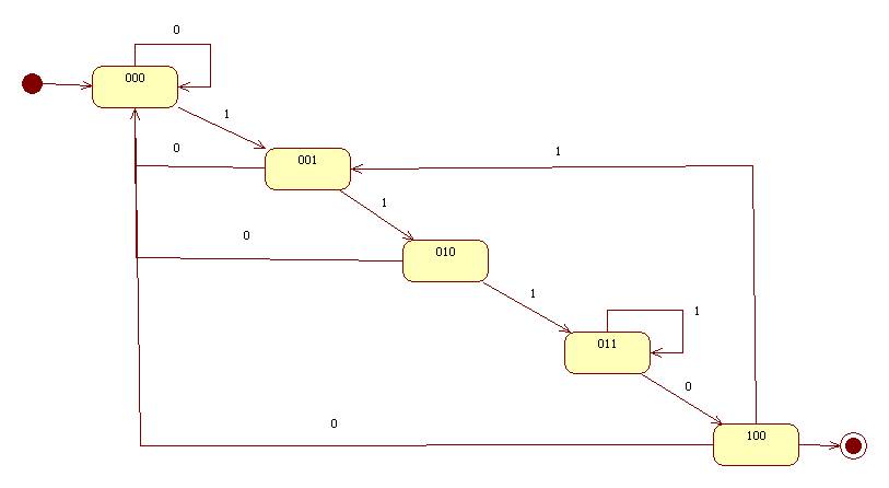
Here's the state table:
|
current state |
x = 0 |
x = 1 |
|
000 |
000 |
001 |
|
001 |
000 |
010 |
|
010 |
000 |
011 |
|
011 |
100 |
011 |
|
100 |
000 |
001 |
Flip Flops
We will need three flip-flops to represent five states. Here's our notation:
F0 = S0/R0:Q0/Q0'
F1 = S1/R1:Q1/Q1'
F2 = S2/R2:Q2/Q2'
Recall:
Qi' = !Qi
Note:
output = Q2
Flip-Flop F0
Values for Q0
The following table shows the values for Q0, the last bit from the state table entries:
|
current state |
x = 0 |
x = 1 |
|
000 |
0 |
1 |
|
001 |
0 |
0 |
|
010 |
0 |
1 |
|
011 |
0 |
1 |
|
100 |
0 |
1 |
Values for S0/R0
From the table above we can derive the necessary values of S0 and R0:
|
current state |
x = 0 |
x = 1 |
|
000 |
01 |
10 |
|
001 |
01 |
01 |
|
010 |
01 |
10 |
|
011 |
01 |
10 |
|
100 |
01 |
10 |
Equations
Write equations showing when S0 = 1 and R0 = 1.
S0 = X && !(!Q2 && !Q1 && Q0) = X && (Q2 || Q1 || !Q0)
R0 = Q0 || !X
Flip-Flop F1
Values for Q1
|
current state |
x = 0 |
x = 1 |
|
000 |
0 |
0 |
|
001 |
0 |
1 |
|
010 |
0 |
1 |
|
011 |
0 |
1 |
|
100 |
0 |
0 |
Values for S1/R1
|
current state |
x = 0 |
x = 1 |
|
000 |
01 |
01 |
|
001 |
01 |
10 |
|
010 |
01 |
10 |
|
011 |
01 |
10 |
|
100 |
01 |
01 |
Equations:
S1 = X && (Q1 || Q0)
R1 = !X || (!Q0 && !Q1 )
Flip-Flop F2
Values for Q2
|
current state |
x = 0 |
x = 1 |
|
000 |
0 |
0 |
|
001 |
0 |
0 |
|
010 |
0 |
0 |
|
011 |
1 |
0 |
|
100 |
0 |
0 |
Values for S2/R2
|
current state |
x = 0 |
x = 1 |
|
000 |
01 |
01 |
|
001 |
01 |
01 |
|
010 |
01 |
01 |
|
011 |
10 |
01 |
|
100 |
01 |
01 |
Equations:
S2 = !X && Q1 && Q0
R2 = !(!X && Q1 && Q0) = X || !Q1 || !Q0