We begin today by looking at how IP packets are forwarded in a network.
In order to understand this it is useful to recall the following things about IP datagrams:
Every IP packet contains the IP address of the destination host.
The "network part" of an IP address uniquely identifies a single physical network that is part of a larger Internet.
All hosts and routers that share the same network part of their address are connected to the same physical network and thus can communicate with each other by sending frames over that network.
The Internet is connected. Further every physical network that is part of the Internet has at least one router that is connected to at least one other physical network; this router can exchange packets with hosts or routers on either network.
To forward a packet a router looks at the network address of the destination and compares it to the network addresses of its interfaces. If it finds a match then it forwards the packet over that interface. Otherwise, it checks if the network address exists in its forwarding tables. If yes, then it forwards according to the table entry. If not, it sends the packet to a default router.
For a host with only one interface and only a default router in its forward table this reduces to: If the network number of the destination is my network number then deliver the packet directly; otherwise deliver the packet to the default router.
Notice that IP is allowing us to be more scalable because we now have a two level hierarchy to get a packet to its destination: we route to the correct network and then use switches in that network to get to the correct host.
Address Translation (ARP)
So far we have explained how IP packets are sent to the correct network.
We still need to explain how they get to the correct host.
The IP address of the destination host is typically different from the kinds of addresses such as Ethernet addresses that
the particular destination network interface cards understand.
To do this a protocol called ARP (Address Resolution Protocol) is used by each host on a network to map between IP addresses and link-level addresses.
The set of mappings held by a given host is called an ARP table or ARP cache.
Since mappings may change over time, entries in these tables have timers associated with them and get timed-out and removed periodically (on the order of 15 minutes).
ARP relies on the fact that many link-layer protocols support broadcast.
If a host wants to send an IP datagram to a host that it knows is on the same network, it first checks for an entry in its table, if it finds an entry it uses it.
Otherwise, the host broadcasts an ARP query on the network.
Each host on the network receives the query and checks to see if it matches its IP address. If it does match, it sends a response message that contains its link-layer address back to the originator of the query. The originator can then add the appropriate entry to its table, and also send the IP datagram.
It should be noted that when a host broadcasts a query message, each other host on the network can learn the sender's link-layer and IP addresses and if they don't have these in their tables they can add them.
ATMARP
ATM networks are often used as part of IP internetworks.
So they too must provide a form of ARP; however, they do not support broadcast. (Remember they are circuit-switched networks.)
ATMARP is the protocol for this and forms part of the so-called classical IP over ATM model.
The basic idea is that ATM networks are split into subnets called logical IP subnets (LISs).
All hosts in the same subnet have the same IP network number.
Two hosts in the same LIS can directly communicate with other; but ones in different LISs cannot.
An ARP server in each LIS is used to maintain a table of mappings between ATM addresses and IP addresses.
Each node in the LIS must be configured to know the ATM address of this ARP server.
When a host boots it is supposed to send its IP address, ATM address information to the server.
If a given host wants to send an IP packet to another host in the same LIS, it makes a VC to the ARP server, gets the
entry, and uses this to make a VC to the desired host.
Host Configuration
Ethernet addresses are globally unique but do not reflect the internetwork structure.
IP addresses need to be globally unique and reflect this structure. So they can't be pre-configured
into a host because a manufacturer can't in general know where you want to connect a host into the Internet.
For this reason, IP addresses need to be reconfigurable. Most OS's provide a means to manually configure the IP information.
If every machine had to be manually configured, this would be a lot of work, and error prone.
DHCP
To solve the problem of manually configured IP addresses, an automated method is typically used. DHCP (dynamic host configuration protocol) is the most common such approach.
DHCP relies on the existence of a DHCP server that is responsible for providing configuration information to hosts.
To contact a DHCP server, a newly booted or attached machine sends a DHCPDISCOVER message (this uses UDP) to 255.255.255.255. This is
a broadcast IP address.
On each network (making use of DHCP) there is at least one relay agent or DHCP server. Relay agents forward DHCPDISCOVER message to a designated DHCP server.
The DHCPDISCOVER message has the host's Ethernet address. The DHCP server responds by sending the message back to the host with its yiaddr (your internet address) field filled. The server adds the Ethernet IP address pair to its table.
In DHCP, IP addresses are leased for a given period of time, after which the lease expires and the server can remove the entry from its tables. Hosts must periodically either renew their leases or get new addresses.
Quiz
Where in a switch does buffering most commonly occur?
At the input ports.
In the fabric.
At the output ports.
Error Reporting (ICMP)
IP is perfectly willing to drop datagrams -- for instance, if the router does not know how to forward the datagram or when one fragment of a datagram fails to arrive at the destination.
IP does not always fail silently.
It is configured with a companion protocol known as ICMP (Internet Control Message Protocol) that defines a collection of error messages that are sent back to the source host whenever a router or host is unable to process an IP datagram successfully.
For example, ICMP defines error messages indicating that the destination host is unreachable, that the reassembly process failed, that the TTL has reached 0, that the IP header checksum failed, and so on.
ICMP can also send some control messages from a router back to a host. One example of this is an ICMP-Redirect, which tells the host that a better route to a destination exists.
Virtual Networks and Tunnels
So far, we have been interested in making it possible for nodes on different networks to communicate.
Sometimes it is useful to be able to only allow a subset of the nodes in the Internet to communicate in what is called
a virtual private network (VPN).
The key building block for a VPN is an IP Tunnel. This is a virtual point-to-point link between a pair of nodes that are actually separated by an arbitrary number of networks.
Such a link has a router at the entrance to the tunnel and a router at the exit of the tunnel.
Whenever the entrance router wants to send data over the link it encapsulates it in an IP packet with a destination IP address of the router on the other end of the tunnel.
So if the original data was an IP datagram, we might encapsulate this datagram in a IP datagram destined for the end of the tunnel.
The routing table entry for a VPN link looks like a standard routing table entry.
Several tunnels can be stuck together to build up a virtual network.
Why bother to use tunnels?
Tunnels can be combined with encryption so that the traffic over the VPN cannot be read by everyone on the internet.
The VPN routers might be able to support protocols (MBone multicast) that standard routers do not.
It allows one to carry packets from different protocols across an IP network.
Routing
We now look at algorithms that enable routers and switches to acquire the information that is in their forwarding tables.
Forwarding is the process of looking at a packets destination address in a table, and sending a packet in a direction determined by that table.
Routing is the process by which forwarding tables are built.
A forwarding table is used when a packet is being forwarded and so must contain enough information to accomplish this function.
A routing table is the table that is built-up by the routing algorithm as a precursor to building the forwarding table.
The two are often kept separate so that the forwarding table can be as fast as possible.
The first algorithms we will consider scale to networks of moderate size.
They are used for intradomain routing protocols (aka interior gateway protocols (IGPs)).
Here a domain is an internetwork in which all the routers are under the same administrative control. For instance, a university campus network or a network of a single ISP.
Network as a Graph
We view a domain as a graph where the nodes are either hosts, switches, routers, or networks and the edges are
network links.
Each edge has an associated cost, which indicates how desirable it is to send data over that link.
The basic problem with routing is to find the lowest-cost path between any two nodes in such a graph.
For a simple network, you could imagine statically computing this and then hard-coding the information into each node.
This approach is not taken in practice because:
It does not deal with node or link failures
It does not consider the addition of new nodes or links
It implies that the edge costs cannot change, even though we might reasonably wish to temporarily assign a high congest to
congested links.
For these reasons, routing is typically achieved by running routing protocols among the nodes.
These protocols provide a distributed, dynamic way to solve the problem of finding the lowest-cost path.
Distance Vector (RIP)
The distance-vector (aka Bellman-Ford) algorithm is one such distributed routing algorithm.
The starting assumption is that each node knows the costs of its directly connected neighbors.
The routing table has entries of the form (Destination, Cost, Next Hop) and is initialized to just these
connected neighbors.
Each router then sends its routing table to each of its directly connected neighbors.
Using this information, the receiving router updates its own table. Here are a couple of cases where a receiving router might have to update its table:
The sending router sends information for a host that the receiving router has never heard of before
The path to some host through the sending router might be cheaper than some existing path.
This process is then repeated until hopefully the routing table converges to a table with routing information for the whole domain.
Routers following distance vector send periodic updates to make sure the routing information is current.
They also send triggered updates whenever a node receives information that causes the nodes tables to be updated.
Problems with Distance Vector
Although distance vector routing does converge to the correct answer, it tends
to do it slowly.
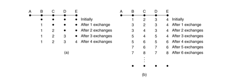
As an example, consider the situations below in a linear network where on the
left A comes alive at some time t and on right where it fails at some later time.
On the left it takes a significant amount of time for all machines to get the
correct distance to A. On the right the machines keep incrementing the
distance to A forever (count to infinity problem):
One approach to solve this is to use a split horizon: You don't send routes you learned from neighbors back to them.
Another problem with Distance Vector routing is that it does not take line
bandwidth into account.