Outline
- Switching and Forwarding
- Datagrams
- Virtual Circuit Switching
- Source Routing
- Bridges and LAN Switches
Switches
- Last day, we started talking about packet switching. We said we were interested in how
switches know which line to forward on and how switches handle congestion.
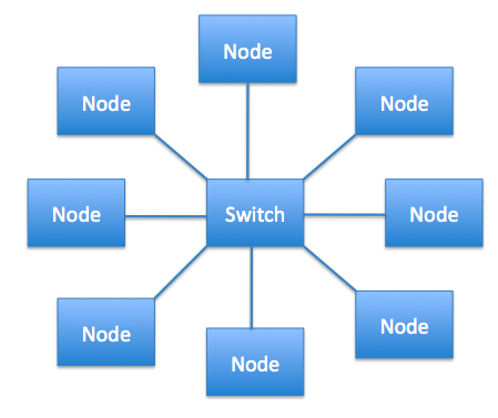
- A switch is multi-input, multioutput device, which transfers packets from an input to one or more outputs.
- In terms of the topologies for networks we've seen so far, we have point-to-point links, Bus (Ethernet), and rings. Switches
add to this a star topology.
- Some advantages of the star topology related to switches include:
- Even keeping the degree of the switch vertex small (even as small degree 3), by connecting several switches, we can build a large network with a complicated structure.
- We can connect switches to each other and to hosts using long-hau,l point-to-point links, which means that we can build networks which span large geographic distances.
- Adding a new host to the network by connecting it to a switch does not necessarily reduce the performance of hosts already connected to the network. So switched networks are considered more scalable than things like a strict Ethernet approach.
Forwarding
- A switch is connected to a set of links. Each link uses a data link layer protocol to communicate with the node or nodes on the other end of the link.
- As an example, a switch might have a T1, a T3, and a STS-1 line coming into it. So the data link protocol is not necessarily the same for each line.
- Where a link comes into a switch is called a port. Each port usually has a number associated with it. i.e., port 1, port 2, etc. of the switch.
- A switch needs to be able to receive data on one link and be able to send it out of the correct outgoing link. This job is called forwarding or switching.
- There are two common approaches to solving the switching decision problem: a datagram (also called connectionless) approach and a virtual circuit (also-called connection-oriented) approach.
- There is also a less common approach called source routing.
- MAC addresses are used to uniquely identify all switches/hosts in a switched network. That is why Ethernet cards have to have a unique address.
Datagrams
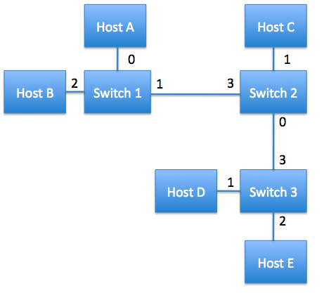
- In this approach, to decide how a switch forwards a packet, the switch consults a forwarding table that it has inside its memory.
- This table consists of two columns one for the destination host and the other for the port to use as the outgoing line. For example, for switch 2 above, the table would look like:
| Destination | Port |
|---|
| A | 3 |
| B | 3 |
| C | 1 |
| D | 0 |
| E | 0 |
More on the Datagram Approach
- In the datagram approach, we can imagine that the network operator configures all the cables and sets up the
the routing table statically.
- For small networks this is possible, but for large, dynamically evolving networks, this is close to impossible.
This harder problem is called routing, and we will talk about routing tables later in the semester.
- Connectionless approaches have the following characteristics:
- A host can send a packet anywhere any time. This contrasts with connect-oriented approaches where a "connection-state" might need to be established first.
- When a host sends a packet, the host does not know if the network is capable of delivering it or if the receiver is even alive.
- Each packet is forwarded independently of the previous packets. Thus, if a forwarding table gets changed between two packets being sent, then the two packets might take different routes through the network.
- A switch or link failure might not have any serious effect if it is possible to find an alternate route around the failure.
Virtual Circuit Switching
- In this approach, a virtual circuit/connection (VC) is set up from the source host to the destination host. Once this connection is established,
data is then sent on this connection.
- This is a two stage process: (1) connection setup and (2) data transfer.
- We will now look at the harder of these, connection setup...
Connection Setup -- VC Table Entries
- In this stage, it is necessary to establish a "connection state" in each of the switches between the source and destination.
- The connection state for a connection consists of an entry in a VC table in each switch through which the connection passes.
- This entry contains:
- A virtual circuit identifier (VCI) that uniquely identifies the connection at this switch, and which will be carried inside the header of the packet that belongs to this connection.
- An incoming interface (i.e., incoming port) on which packets for this VC arrive at the switch.
- An outgoing interface (i.e., outgoing port) in which packets for this VC leave this switch
- A potentially different VCI will be used for outgoing packets.
- Given a packet, a switch, by looking at the VCI in its header, can find the corresponding entry in its VC table, and then use the correct outgoing line. Before sending on this outgoing line the VCI in the header of the packer is set for the next switch.
- The VCI is only significant for one link in the circuit path. That's why each link we change the VCI.
Connection Setup -- Setup algorithms
- There are two main approaches to setting up connection states in the switches.
- The network administrator manually sets up the connection link for each switch in the circuit. That is, a permanent virtual circuit (PVC) is established.
- A host can send signalling messages into the network to cause the state to be established. This establishes a switched virtual circuit (SVC).
- Let's look at the second approach. To do signalling, host A sends a message into the network, say to switch 1, with which it is connected. This message contains the complete destination address of host B to which A wants to send data.
- We assume the network is smart enough to be able to propagate the signalling message all the way to Host B. Each switch the
message goes through sets up a VC entry. The task of assigning a VCI value for the incoming port through which message was sent is up to the switch. The outgoing VCI is at this point empty and will be determined by the next switch in the route.
- Note VCI values might be significantly smaller than the 6 bytes used for Ethernet address.
- Once the signalling packet reaches B, an acknowledgement packet is sent back to A. This packet traverses the connection just established back to A. As it does the outgoing VCI's of the in between switches are set up based on the value in the acknowledgement packet.
More on Virtual Circuit Switching
- Once the connection is established for the SVC, data can be transferred along this connection just as in the PVC approach.
- When A no longer needs the connection, it can tear down the connection by sending a tear down message to the first switch along
this connection.
- This switch would remove the VC table entry for the connection and send along the tear-down message to the next switch in the connection...
- There are several things to note about virtual switching:
- There is at least one RTT before data can be sent.
- Although the connection request message needs to have the full address of B, thereafter, each packet from A only needs the much smaller VCI of the next switch in the link.
- If any switch in the connection fails, the whole connection fails, and a new connection needs to be established.
- You still need some kind of routing algorithm to send the connection message in the first place. We will talk about how to do this when we cover Chapter 4.
- If a connection can be established then Host A knows Host B is alive and is willing and able to receive data from A.
Resource Allocation
- During the connection setup phase, it is also possible to allocate resources to the service.
- As an example of this, consider what is done in an X.25 network (a connection-oriented network that used to be
used by the telephone companies):
- Buffers are allocated to each virtual circuit when the circuit is initialized.
- The sliding window protocol is run between each pair of nodes in the VC, and this is augmented with flow control
so that the sender on each link does not send too fast and overrun the buffers on the receiving node.
- The circuit is rejected by a given node if not enough buffers are available at that node when the connection request message is processed.
- So in X.25, each node is ensured of having the buffers needed to queue packets that arrive on that circuit. This is called hop-by-hop flow control.
Final Remarks on Virtual Circuits
- A datagram network in contrast to a virtual circuit network has no connection establishment phase. Each packet that arrives, regardless from whom, competes for buffer space with all other packets.
- In the virtual circuit model, one could imagine providing each circuit with its own level of Quality of Service. We will talk about QoS again when we describe the transport layer.
- In addition to X.25, some popular virtual circuit technologies are frame relay and ATM.
- Frame relay is somewhat lighter weight than X.25. Maybe network service providers provide Frame Relay PVC services which can be used to construct Virtual Private Networks, which we'll discuss when we cover Ch 4.
Source Routing
- The idea in this strategy is that the source host provides all the information in the packet to switch the packet to the destination.
- One way to implement this is to put an ordered list of switch ports in the header of the packets.
- The first element in this list says which outgoing port the first switch should use, the second element says which outgoing port the second switch should use, and so on.
- For this to work:
- The sender needs to know enough about the network topology to form the header for the path. This is somewhat similar to the problem of figuring out where to send the setup packet in a VC.
- The header may be of variable length depending on its destination
- At each switch, we need to modify the header. We could either strip off a port number or we could rotate the list of port numbers, or use a pointer to say which element in the list the next switch should use.
- Source routing can be used in both the datagram and VC network setting.
- The IP protocol provides a source routing option.
- In the VC setting, it is sometimes used to get the initial signalling message to its destination.
- One can either have "strict" or "loose" source routing. What we described above was strict. If we only specify
certain "waypoint" switches that need to be traversed, than we are doing "loose" source routing.
Bridges and LAN Switches
- We now look at the class of switches which are used to forwards packets between shared media LANs such as Ethernets.
- Suppose you have a pair of Ethernets that you want to connect.
- If you use a repeater, you might exceed the physical limitations of the Ethernet.
- Another approach is to put a node between the two Ethernets and have the node forward frames transmitted on either side of the Ethernet.
- This node operates in promiscuous mode, accepting all frames transmitted on either side.
- This kind of node is called a bridge.
- The LANs connected by one or more bridges are together called an extended LAN.
- On Monday, we will discuss bridges in more detail.


