Outline
- Switching and Forwarding
- Virtual Circuit Switching
- Source Routing
- Bridges and LAN Switches
- Spanning Tree Algorithm
Virtual Circuit Switching
- In this approach, a virtual circuit/connection (VC) is set up from the source host to the destination host. Once this connection is established,
data is then sent on this connection.
- This is a two stage process: (1) connection setup and (2) data transfer.
- We will now look at the harder of these, connection setup...
Connection Setup -- VC Table Entries
- In this stage, it is necessary to establish a "connection state" in each of the switches between the source and destination.
- The connection state for a connection consists of an entry in a VC table in each switch through which the connection passes.
- This entry contains:
- A virtual circuit identifier (VCI) that uniquely identifies the connection at this switch, and which will be carried inside the header of the packet that belongs to this connection.
- An incoming interface (i.e., incoming port) on which packets for this VC arrive at the switch.
- An outgoing interface (i.e., outgoing port) in which packets for this VC leave this switch
- A potentially different VCI will be used for outgoing packets.
- Given a packet, a switch, by looking at the VCI in its header, can find the corresponding entry in its VC table, and then use the correct outgoing line. Before sending on this outgoing line the VCI in the header of the packer is set for the next switch.
- The VCI is only significant for one link in the circuit path. That's why each link we change the VCI.
Connection Setup -- Setup algorithms
- There are two main approaches to setting up connection states in the switches.
- The network administrator manually sets up the connection link for each switch in the circuit. That is, a permanent virtual circuit (PVC) is established.
- A host can send signalling messages into the network to cause the state to be established. This establishes a switched virtual circuit (SVC).
- Let's look at the second approach. To do signalling, host A sends a message into the network, say to switch 1, with which it is connected. This message contains the complete destination address of host B to which A wants to send data.
- We assume the network is smart enough to be able to propagate the signalling message all the way to Host B. Each switch the
message goes through sets up a VC entry. The task of assigning a VCI value for the incoming port through which message was sent is up to the switch. The outgoing VCI is at this point empty and will be determined by the next switch in the route.
- Note VCI values might be significantly smaller than the 6 bytes used for Ethernet address.
- Once the signalling packet reaches B, an acknowledgement packet is sent back to A. This packet traverses the connection just established back to A. As it does the outgoing VCI's of the in between switches are set up based on the value in the acknowledgement packet.
More on Virtual Circuit Switching
- Once the connection is established for the SVC, data can be transferred along this connection just as in the PVC approach.
- When A no longer needs the connection, it can tear down the connection by sending a tear down message to the first switch along
this connection.
- This switch would remove the VC table entry for the connection and send along the tear-down message to the next switch in the connection...
- There are several things to note about virtual switching:
- There is at least one RTT before data can be sent.
- Although the connection request message needs to have the full address of B, thereafter, each packet from A only needs the much smaller VCI of the next switch in the link.
- If any switch in the connection fails, the whole connection fails, and a new connection needs to be established.
- You still need some kind of routing algorithm to send the connection message in the first place. We will talk about how to do this when we cover Chapter 4.
- If a connection can be established then Host A knows Host B is alive and is willing and able to receive data from A.
Resource Allocation
- During the connection setup phase, it is also possible to allocate resources to the service.
- As an example of this, consider what is done in an X.25 network (a connection-oriented network that used to be
used by the telephone companies):
- Buffers are allocated to each virtual circuit when the circuit is initialized.
- The sliding window protocol is run between each pair of nodes in the VC, and this is augmented with flow control
so that the sender on each link does not send too fast and overrun the buffers on the receiving node.
- The circuit is rejected by a given node if not enough buffers are available at that node when the connection request message is processed.
- So in X.25, each node is ensured of having the buffers needed to queue packets that arrive on that circuit. This is called hop-by-hop flow control.
Final Remarks on Virtual Circuits
- A datagram network in contrast to a virtual circuit network has no connection establishment phase. Each packet that arrives, regardless from whom, competes for buffer space with all other packets.
- In the virtual circuit model, one could imagine providing each circuit with its own level of Quality of Service. We will talk about QoS again when we describe the transport layer.
- In addition to X.25, some popular virtual circuit technologies are frame relay and ATM.
- Frame relay is somewhat lighter weight than X.25. Maybe network service providers provide Frame Relay PVC services which can be used to construct Virtual Private Networks, which we'll discuss when we cover Ch 4.
Source Routing
- The idea in this strategy is that the source host provides all the information in the packet to switch the packet to the destination.
- One way to implement this is to put an ordered list of switch ports in the header of the packets.
- The first element in this list says which outgoing port the first switch should use, the second element says which outgoing port the second switch should use, and so on.
- For this to work:
- The sender needs to know enough about the network topology to form the header for the path. This is somewhat similar to the problem of figuring out where to send the setup packet in a VC.
- The header may be of variable length depending on its destination
- At each switch, we need to modify the header. We could either strip off a port number or we could rotate the list of port numbers, or use a pointer to say which element in the list the next switch should use.
- Source routing can be used in both the datagram and VC network setting.
- The IP protocol provides a source routing option.
- In the VC setting, it is sometimes used to get the initial signalling message to its destination.
- One can either have "strict" or "loose" source routing. What we described above was strict. If we only specify
certain "waypoint" switches that need to be traversed, than we are doing "loose" source routing.
Bridges and LAN Switches
- We now look at the class of switches which are used to forwards packets between shared media LANs such as Ethernets.
- Suppose you have a pair of Ethernets that you want to connect.
- If you use a repeater, you might exceed the physical limitations of the Ethernet.
- Another approach is to put a node between the two Ethernets and have the node forward frames transmitted on either side of the Ethernet.
- This node operates in promiscuous mode, accepting all frames transmitted on either side.
- This kind of node is called a bridge.
- The LANs connected by one or more bridges are together called an extended LAN.
Learning Bridges
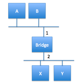
- If A wants to send to B, there is no point for the bridge to forward the message it sees on port 1 to port 2. How does the
bridge know when to forward and when not to?
- A human could create a bridge table with two columns, one for host, one for which port to use. If the frame comes in on the same port
that it should also go out on, then the bridge wouldn't need to forward it.
- This would be using the datagram model of forwarding we talked about last day.
- One way to automate the process of building the bridge table is the following:
- When a bridge first turns on, it starts with an empty table.
- When the bridge gets a frame on a given interface, it checks its table to see if there is an entry which has the same source address. If not, it adds the entry (source address, interface) to its table and sets a timer. If yes, and the entry would be the same, the timer is reset.
- The bridge then checks: Does the destination MAC address have an entry in the table? If yes, and it is different from the incoming interface, forward the frame according to the entry. If there is no entry, then forward on all outgoing lines other than the one the frame came in on.
- If a timer goes to 0, then delete that entry. This guards against machines going down or changing the topology.
Spanning Tree Algorithm
- The algorithm two slides back works provided there are no loops in the network graph. If there is a loop, and no one has an entry
for a given frame destination, then a frame might cycle indefinitely.
- This is a problem because, loops occur reasonably naturally in bridged networks: They might arise because no one person building the network controls all the bridges; they also might arise because the builder wanted to ensure the reliability of the network against failures.
- In order to solve this problem, the bridges might run a distributed spanning tree algorithm. This algorithm was developed at DEC by Radia Perlman and is part of the 802.1. spec.
- Once a spanning tree is computed, a bridge can use the algorithm of two slides back with the change that it only forwards on ports which are part of the spanning tree.
- The spanning tree algorithm works as follows:
- Each bridge has its own unique ID (MAC address of lowest port + bridge priority, 8 bytes) which we denote B1, B2, B3 ...
- The bridges first elect a root bridge. This will be the bridge with the least ID.
- Each bridge then computes the shortest path to the root, and determines which of its ports is on this route. It also determines a designated forwarding bridge which will be responsible for forwarding messages to the route.
More on the Spanning Tree Algorithm
- In order to do each of these steps, bridges exchange configuration messages containing: (1) the ID of the bridge sending the message, (2) the ID for what the sending bridge thinks is the root bridge, (3) the distance in hops of the sending bridge from the root.
- If a bridge receives a configuration message, it checks if its own configuration message is better or worse than the one received.
- The new message is better if:
- It identifies a root with a smaller ID.
- It identifies a root with an equal ID, but shorter distance.
- The root ID and distance are equal but the sending bridge has a smaller ID.
- If the new message is better than the currently recorded information, a bridge discards the old information and saves the new information. However, it adds 1 to the distance from the root to the bridge.
- When a bridge receives a message which tells it that it is not the root, it stops generating its own configuration messages, and instead only forwards messages from other bridges, adding 1 to the hop distance.
- When a bridge receives a message which tells it that it is not the designated bridge for the port of its neighbor, the bridge stops sending configuration messages over that port.
- The system stabilizes when only the root bridge is still generating messages. The root continues to do this periodically.
- If any node including the root goes down, downstream nodes will stop receiving configuration messages and then after a timeout period will once again claim to be root and run the above algorithm. This also happens if new nodes are added to the system.
Broadcast and Multicast
- To broadcast in a bridge network, a given bridge only needs to send out the frames it receives on each of its active ports other than the port on which it received the frame.
- On today's extended LANs, multicast is implemented in the same way as broadcast and it is up to each host to decide whether or not to accept a given frame.
- It might be the case that not all LANs in a given extended LAN have a host that needs to be multicast to. Another proposed way to implement multicast is for each host to periodically send a frame with the address for the multicast group in its source field and have the multicast
address in its destination field. Bridges could then use the table algorithm to learn only those LANs that have hosts for that multicast address.
Limitations of Bridges
- The set-up of the previous few slides can be used to create networks of tens of bridges.
- The set-up does not scale to larger networks for a variety of reasons.
- One problem is that if a destination is unknown it has to be broadcast. As the network gets bigger there are more unknown hosts, and this becomes more and more of an issue.
- Another reason is that the spanning tree algorithm scales linearly in the number of nodes, so will take longer and longer to settle. It would
be useful to have a hierarchy of bridges to solve this.
Virtual LANs
- One way to try to make extended LANs more scalable is to use virtual LANs (VLANs).
- Each VLAN is assigned an identifier (a color).
- Packets can only be sent from one segment to another if they have the same color.
- This makes it possible to do things like have a VLAN for the CS department as part of the extended LAN of the Science college. CS traffic on this VLAN wouldn't go to the Math department's VLAN (also on Science's LAN)and so they wouldn't see our private messages.
- The implementation of VLANs is specified in the 802.1Q spec. This spec changes the way Ethernet frames look to VLAN enabled bridges. It is backward compatible for non-such enabled bridges and hosts. Basically, before the length field in the frame 0x8100 is added, followed by a priority field, followed by a canonical format indicator, followed by the VLAN identifier.
Heterogeneity
- As bridges make use of the frame header, they are limited to connect networks which have the same format for addresses.
- So bridges could be used to interconnect Ethernets and Token rings. But they could not be used to connect to ATM networks.
- So there are limitations on the heterogeneity of the networks you can use with bridges.


