Outline
- User Interfaces for Rotations
- Blender
Introduction
- Last day, we said we often use the mouse to specify object motion in a graphics application.
- We started considering two user interfaces for specifying rotations: arcball and trackball and I mentioned some things verbally about them.
- Today, we begin considering these interfaces in more detail.
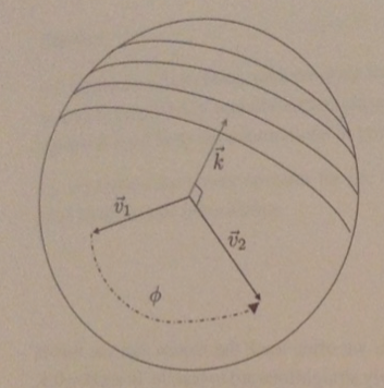
- To start we imagine a sphere of some chosen radius that is centered at `tilde o`, the origin of `vec bb o^t`.
- Suppose the user clicks on the screen at some pixel `s_1` over the sphere in the image; we can interpret this as the user selecting some 3D point `tilde p_1` on the sphere.
- If the mouse is then moved to `s_2` over the sphere, we interpret this as a second point `tilde p_2` on the sphere.
- Given these two points, define the two vectors `vec v_1`, `vec v_2` as the unit length vectors in the directions `tilde p_1 - tilde o`, `tilde p_2 - tilde o`. Define the angle `phi = arccos(vec v_1 cdot vec v_2)`
and the axis `vec k = mbox(normalize)(vec v_1 times vec v_2)`.
- We are now ready to define our interfaces...
Trackball and Arcball Interfaces
- In the trackball interface, we define `M` as the rotation of `phi` degrees about the axis `vec k`.
- In the arcball interface, we define `M` as the rotation of `2phi` about the axis `vec k`.
- In quaternion notation, the rotation `2phi` about `vec k` can be represented as:
`[[cos phi],[sin phi hat bb k]] = [[hat bb v_1 cdot hat bb v_2],[hat bb v_1 times hat bb v_2]] = [[0],[hat bb v_2]][[0],[-hat bb v_1]]`
where `hat bb k`, `hat bb v_1`, `hat bb v_2` are the coordinate 3-vectors representing the vectors `vec k`, `vec v_1`, and `vec v_2` with respect to the frame `vec bb a^t`, the auxiliary frame we said was good a while back for doing affine transformations.
Interface Properties
- The trackball interface is natural in the sense that the user simply grabs a physical point on a sphere and drags it around.
- Unfortunately, if the user first moves from `s_1` to `s_2` and then from `s_2` to `s_3`, the composed trackball rotations will be different from the result of moving the mouse directly from `s_1` to `s_3`.
- In both cases, the point `tilde p_1` does move to `tilde p_3`, but the two results can differ by some "twist" about the axis `tilde o - tilde p_3`.
- On the other hand, for arcball, objects appear to spin twice as fast as expected.
- Nevertheless, the arcball interface is path independent.
Path Independence of Arcball
- If we compose two arcball rotations, one corresponding to motion from `tilde p_1` to `tilde p_2` and the other from `tilde p_2` to `tilde p_3`, then we get:
`[[hat bb v_2 cdot hat bb v_3],[hat bb v_2 times hat bb v_3]] [[hat bb v_1 cdot hat bb v_2],[hat bb v_1 times hat bb v_2]]`
- This is because both rotations are applied with respect to the frame `vec bb a^t`, which is unchanged by these operations.
- Expanding
`[[hat bb v_1 cdot hat bb v_2],[hat bb v_1 times hat bb v_2]] = [[0],[hat bb v_2]][[0],[-hat bb v_1]]`
and similarly, for the `hat bb v_2`, `hat bb v_3` case, we get that out product is:
`[[0],[hat bb v_3]][[0],[-hat bb v_2]][[0],[hat bb v_2]][[0],[-hat bb v_1]] =
[[0],[hat bb v_3]][[0],[-hat bb v_1]] = [[hat bb v_1 cdot hat bb v_3],[hat bb v_1 times hat bb v_3]]`
which is exactly what we would have gotten has we moved directly from `tilde p_1` to `tilde p_3`.
Implementation
- Trackball and arcball can be directly implemented using either 4x4 matrices or quaternions to represent the transformation `M`.
- Since all of the operations are on vectors, not points, the origin of the coordinate system in unimportant, and will work in any coordinate system that shares the axes of `vec bb a^t`. i.e., eye coordinates.
- One problem might be to calculate the point on the sphere corresponding to a selected pixel. This is essentially the ray tracing problem that we will talk about in CS116b.
- One approximate solution is to use "window coordinates". In this case, the x-axis is the horizontal axis of the screen, the y axis is the vertical axis of the screen, the z axis is the direction coming out of the screen.
- We think of the sphere's center as simply sitting on the screen.
- Given the `(x,y)` window coordinates of the point where the user has clicked, we can easily find the `z` coordinate using the equation `(x - c_x)^2 + (y-c_y)^2 +(z - 0)^2 - r^2 =0` where `[c_x, c_y, 0]^t` are the window coordinates of the center of the sphere.
- This still requires computing the center of the sphere in window coordinates, as well as its projected radius on the screen. We will talk about projections needed for this later in the semester. The book's web site has code for this though.
Blender
- Blender is a free, open-source 3D computer graphics modeling/animating software.
- It was initially released in 1995 by Dutch firm Neo Geo, released as shareware until this company went bankrupt in 2002. After which, it was open source by its creditors for a one time payment.
- It has been undergoing continuous development since its original release.
- It is currently maintained by the Blender foundation.
- Blender has been used in movies (Secret of the Kells), on the History channel for animations, and in some games (it has a built-in game engine).
- We are going to briefly look at it today as an example of 3D modeling software.
- Our example will be pretty basic. Creating a initial set of objects in 3-space, adding materials to them, a texture example for one of the materials, and then showing how to render the result.
Using Blender
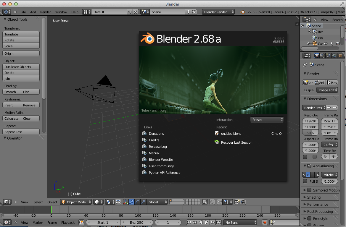
- After downloading Blender and launching it you might get a screen like the above.
- Notice on the splash portion there is a link to the manual which can be useful.
- I will refer to portions of the Blender window as panels. In the Blender Manual's terminology, it calls these portions of the window, windows which I find confusing.
- The toolbar panel at the top of the blender window is called the Info panel. IT has
a File menu item lets you load and save projects, import and export models. It also has link to User Preferences.
- If one clicks on User Preferences, then Input one after opening the tree view a bit, see:
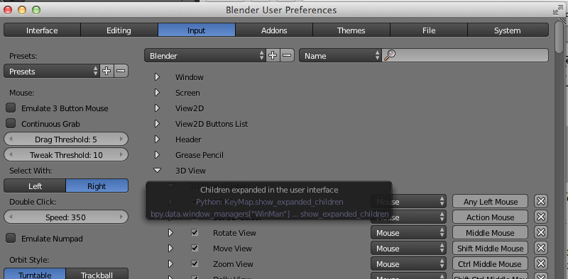
- This allows one to control which keys/mouse gestures map to what. This can be useful for finding out what does what. It is also useful if you have a MacBook Pro which doesn't have a number pad, so that one can remap things.
Moving around the Scene/Panels
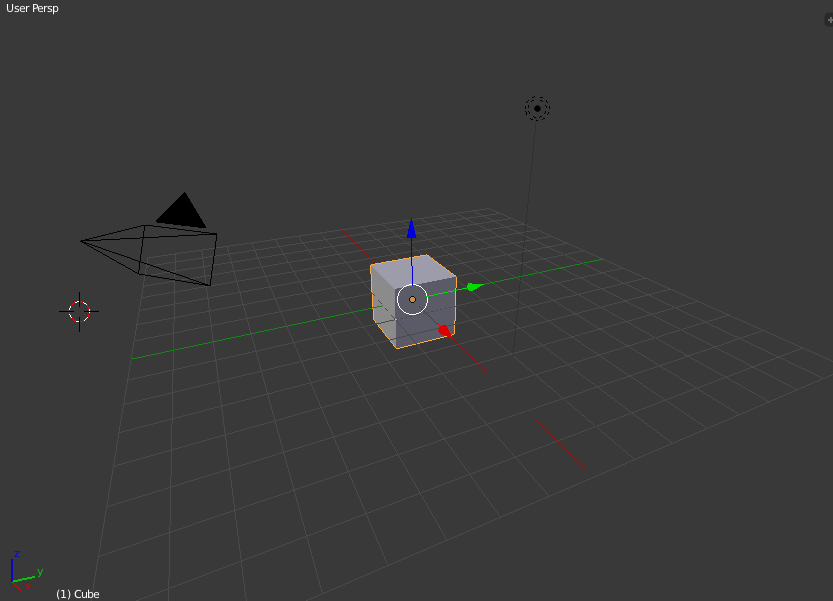
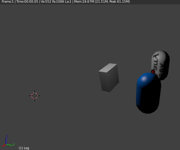
- The center panel of the Blender user interface will initialize to the above. It is called the 3D scene panel
- It technically also includes the Object Tools that one sees on the left hand side of our blender picture from the previous slide.
- The pyramid one sees in the image above with the triangle above it, is a camera position, with up direction.
- The double dotted circle with a line coming down from it is a light.
- Initially, a cube is drawn at the origin; from the top right we can see we are in User Persp mode.
- In the center panel, we can move around the scene by right clicking and moving around (two finder moving around on Mac trackpads). To fly in and out, one can middle click and move the mouse (CTRL - two finger move on Mac).
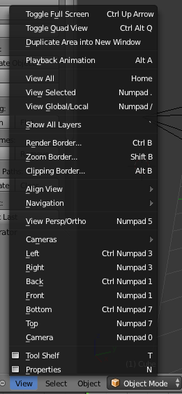
- Beneath this panel is a toolbar with View on it. Clicking on this we see the following menu which would let us change the perspective.
Outliner Panel
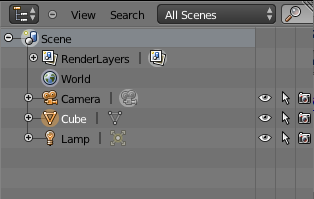
- On the top right of the Blender window is the panel, we see above which we will call the Outliner Panel.
- The Outliner Panel has a tree representation of all the things/objects in our scene.
- Double clicking on a word like cube, we could change its name to something meaningful like "building" or "leg" if we want.
- By dragging things in the outline to other locations, let's you set which object are parents of which other objects.
- Changing things in one panel in Blender will affect what we see in other panels.
- Let's try this by right-clicking on the cube in the Outliner panel, deleting it, and seeing it disappears in the 3D Scene panel.
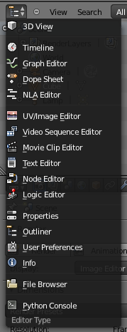
- Notice the little Outline icon in the top right, if we wanted to make this panel into some other panel we could have clicked on it and selected a different panel.
Adding Objects

- By clicking around in our 3D View panel we can set the above cross hairs at different location
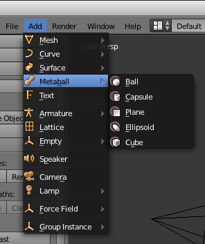
- Then if we use the toolbar at the top of Blender next to File we see the Add menu. Clicking on this, we see many different kinds of things we can add to our scene:
- Selecting one will put the object in our 3D scene at the location of our cross hairs.
Changing an Objects Location, Rotation, Scale
Once an object is on the screen we can then move it around. There are a few different ways we can do this.
By default, if we right click on an object, we can then drag it around on the screen.
We can also use the Object Tools sidebar on the left hand side of the 3D Scene panel.
In this sidebar we can select a transformation we want from: translate, rotate, scale. Then if we click on an object and move that action is done on the object.
Lower down on the sidebar there will also appear the current values for the current transform. We can actually click on these and enter them using numbers.
Alternatively, on the upper right corner of the 3D Scene panel there is a plus sign pullout that looks like:

Clicking this will open a right sidebar that contains info about the transforms on the current object which you can adjust.
Yet another way to adjust the transformations applied to an object is to first click on the object in the Outliner. Then beneath the Outliner, notice the following Property Panel Header strip on which one clicks on the cube.
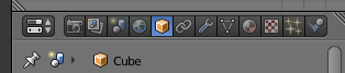
Once the cube is clicked, property panel will display several things about the object including its Transform which you can then edit.
More on Moving Things Around
- Panels in Blender typically have a header. For some panels, such as the 3D View Panel, this header is at the bottom not top of the panel. In which case, I prefer to call it a footer.
- The 3D View Panel footer, has a 3D Manipulator Gadget (red rectangle below) which is perhaps the easiest way to control how things are moved around and rotated:

- The three vector axis icon, basically expands or closes the list of the three available tools. The dropdown menu at the end affects how the tool works.
- If the arrow tool is selected then clicking on an object and dragging moves it around
- If the arc tool is selected, then clicking on an object and dragging rotates it.
- If the box arrow tool is selected, then clicking on an object and dragging changes its size/scale in that direction
- As an example of how things in the dropdown work, when one selects Normal from the drop down, then when one uses the arrow tool and clicks and drags one of the axis arrows of an object, the object moves in a straight line along that axis, with the box arrow toool clicking and dragging the axis gets it to scale in a straight line. For rotations selecting gimbal from the dropdown lets you rotate the object as if it were on gimbals.
Adding Materials to an Object to Change its Color
- To change an object's color, we first select the object in any of the panels. We have already seen how to do this in the 3D Scene Panel and in the Outliner Panel. It can also be selected in the Property Panel via the dropdown under the panel header.
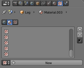
- Next we click on the Property Panel header Material icon and see
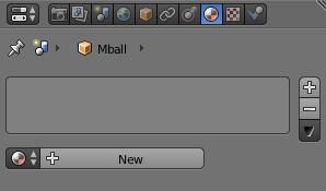
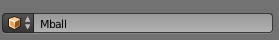
- Clicking on the circle under the text area would allow us to pick an existing material for our object, click on the New would create a new material and add it to the object.
- Once we have created a material, it appears in the text area and it becomes selected in the text area.
- If we had multiple materials we could select a different one from the text area if we wanted.
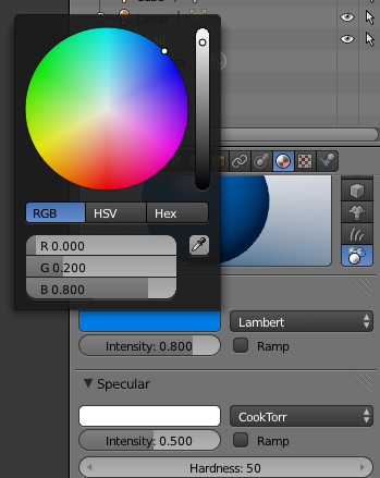
- When a material is selected, its properties appear in the rest of the panel.
- First, one sees a preview of the object, then beneath this controls for changing the the diffuse, specular, and shading properties of the object. Clicking on the color bars of these pops up a color pinwheel that allows you to select a color for the material.
- We will talk about these properties after the midterm roughly Diffuse is what you probably what to edit first. This is color which is reflected off the surface in all directions. Specular controls the color that would be reflected in a specific direction as say from a light.
Adding a Texture to an Object
- Sometimes rather than just setting an object's color we want to apply an image to a object, or make an object "rough". We can do this with a texture.
- To set a texture for an object which doesn't have one, but which does have a material, we first select that object's material.
- Then on the Property Panel header we select the Texture Icon. If the object does not have a texture we will see:
- If we click New, the properties of the material will appear below the button. The first of these is Type. Choose using the drop down the type Image Or Movie, so one sees:
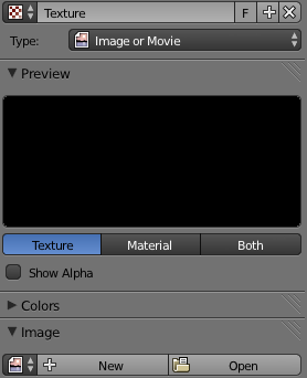
- Under the Image Property, click open, and use the file picker to choose the image file you would like for your texture. You won't be able to see the texture applied to the object unless one sees the "rendered scene" which we will describe on the next slide.
Rendering a Scene
- There are several ways that Blender can draw a scene in 3D View. To change the method,
one can select the Viewport Shading gadget in the 3D View Footer
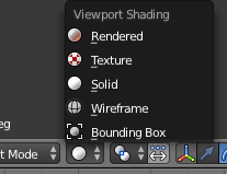
- The default method we have been using is "Solid". Selecting "Rendered" will draw the scene in the viewport using the current lighting model settings and applying textures. It tends to be slower, but still allows one to move around in the 3D Scene.
- If you would like to change the background, "sky" colors in the scene one can click on the world icon in the Property Panel Header and edit these colors there.
- To render the scene from the vantage of the current camera in a high quality fashion suitable for generating an image to save, click on the Render menu in the Info Panel and select Render Image.
- By default this will use a faster rendering called Blender Render, which uses a simple lighting model. To do ray tracing, one can in the Info Panel select the far right dropdown with Blender Render on it and instead select Cycles Render.
- After rendering the Image the 3D View Panel becomes a UV/Image panel. Clicking on the UV/Image icon in the footer of this panel allows one to select 3D View again. In the UV/Image Panel footer there is an Image menu, from here one can save an image of the rendered scene.


