9. Requirements Modeling
During the Analysis Phase the developer, client, users, and other stakeholders work together to produce a specification document, which will be the input to the design phase. A typical specification document includes the following sections:
Introduction
Requirements Model
Functional Requirements
Elaborations
Non-Functional Requirements
Domain Model
Deployment Model
Schedule
Glossary
The introduction is an informative, readable overview of the system to be developed. Many people never read beyond this point.
The requirements model describes the functional and non-functional requirements of the system. More on this below.
The domain model describes the application domain-- the real world context of the system under development. The domain model captures the important concepts and relationships that impact the system. Class and object diagrams are used as domain models.
The deployment model describes the assignment of system components to computers and other devices on a network. More on this later.
The schedule lists the project milestones in the order they will be attacked along with an estimate of the number of man-hours, days, or weeks needed to complete the milestone.
Milestone Man-Weeks
R1, R3, R4 6
R2, R7 3
R8 - R10 2
Milestones are simply groups of requirements. High priority and high risk requirements appear early in the schedule. The schedule will be used to estimate the cost of the project. Scheduling is a highly-inexact science.
The glossary defines application domain terms. Sometimes a misunderstanding over terminology can be the source of a bug. For example, a matriculation system keeps track of the progress students at a university make toward their degree objectives. But what is the definition of a student? Does the system track extension students? Students who stop out for several semesters? Part-time students? Probationary students?
Student: For purposes of the Student Matriculation Tracker (SMT), a student is any person currently enrolled in 12 or more units, and who has enrolled in 12 or more units for at least the previous three semesters with at least a 2.0 GPA. Extension students aren't included in this definition.
Capturing Requirements
The requirements model is the result of a sub-phase of analysis called Requirements Capture. During this phase the developer interviews clients, users, and other stakeholders. Similar systems are researched, and literature surveys are conducted.
During this phase two types of requirements are captured:
The system must run on the Windows NT platform with Internet access. It must be implemented in C++. It must be able to perform 1000 trasnactions per minute, and the mean time between failures must be at least one month.
The system must allow customers to place and track orders. Customers who don't know exactly what they want should be able to browse the online product catalog. Customers should be able to pay for their orderds online using any major credit card.
The first example is a non-functional requirement. It gives us no information about what the system actually does. The second example is a functional requirement. It describes several functions the system must perform.
It's important for the developer to keep the distinction between functional and non-functional requirements clear. The distinction often isn't appreciated by clients and users. The requirements model section of our specification document is divided into two subsections-- one for functional requirements, the other for non-functional requirements.
Functional Requirements
Technically, a functional requirement describes some function that the system computes. We can understand this as a mathematical function of the form:
f: Event* -> Action*
where
Event* = the set of all sequences of user input events or messages, such as entering a command, selecting a menu item, pressing a button, etc.
Action* = the set of all sequences of system actions, such as computing a result, displaying an error message, prompting the user for more input, disabling a menu item, etc.
An action is usually the system's response to a user input event. For example, if the user sends a calculator the sequence of messages:
4, 2, +, 1, 8, =
the calculator responds with the sequence of actions:
read arg1, read arg2, result = arg1 + arg2, display result
The behavioral psychologists of the early Twentieth Century believed mental states and processes were unobservable and therefore weren't legitimate subjects for scientific study. Instead, they based their theories on carefully recorded observations of stimulus-response chains: when the bell rings (stimulus), the dog salivates (response). Specifying a system or function is like a behavioral psychology experiment. We can't observe the internal states or processes of a system that hasn't been built yet, so instead we base our description of the system (i.e., the functional requirements section of the specification document) on carefully recorded stimulus-response chains. We will refer to these stimulus-response chains as event-action sequences or scenarios.
Sometimes we can do better than stimulus-response chains. For example, a typical trigonometry book describes the sine function mathematically, in terms of circles and right triangles, without ever describing an algorithm for computing the sine of a number.
In practice, the functions computed by a commercial software system are often too complex or too ambiguous to be completely specified by mathematical definitions. Also, Mathematical definitions might be too technical for a specification document, which needs to be understood by clients as well as developers. Nevertheless, developers should keep the mathematical definition of a function in mind as an idealized goal of the specification process.
Use Cases
In UML functional requirements are called use cases. A use case diagram shows the system use cases, their relationships to each other, and to the actors (users) who invoke them.
Here is a partial use case diagram for a calculator:
The elliptical icons are the use cases. The stick figures are the actors who interact with the calculator.
Actors
An actor can be a human (User, Engineer, Accountant) or a remote system (Printer). Actors are classes. For example, a particular user, Dilbert, can be regarded as an instance of the Engineer class. As such actors can have the same relationships between them as the classes in a class diagram. Note, for example, the specialization relationship between Accountant and User.
The arrow connecting an actor to a use case is called an actor association. For example, the arrow connecting User to the Enter Number use case says that Users and Enter Number will interact (stimulus-response, press keys-display digits) to accomplish the task of entering a number. The direction of the arrow indicates who begins the interaction. For example, if the calculator is connected to a printer, then the Display Number use case initiates the interaction with the printer.
Generalization
Although a use case describes a function, use cases bare some resemblance to classes. For example, if we identify a use case with a function declaration:
double sin(double x);
Then we can think of calls to this function as use case instances:
sin(pi/2);
sin(-3 * pi/8);
sin(0);
UML pushes this analogy. For example, UML uses the generalization arrow to connect a use case with special cases:
Of course a user can create and send a new email message, but forwarding or replying to an email message are special cases of sending an email message. Although the user command for reply and forward are different from send, we don't need to show actor associations to these use cases, because here, as in a class diagram, the generalization arrow implies inheritance. In particular, the Forward, Reply, and Reply All inherit the user association from the Send use case, as well as the "includes" relationship to the Edit use case.
As with classes, we can also define abstract use cases. In our calculator example Apply Function, Trig, Finance, and Arithmetic are abstract use cases. It doesn't make sense for the user to instantiate (i.e., invoke or call) the Trig use case. Rather the user instantiates the Sine, Cosine, and Tangent use cases that specialize the Trig use case. (These use cases are not shown in our diagram.) Some CASE tools allow developers to stereotype abstract use cases. Abstract use cases are handy when they describe a cohesive family of use cases to which they can bequeath relationships to other use cases and actors.
Includes and Extends
If we push the analogy between use cases and functions, then we can think of the includes relationship between use case A and use case B as the relationship "function A calls supporting function B."
The arrow points from the caller, A, to the supporting function, B. As a supporting function, B normally wouldn't have actor associations, and would normally be included by two or more use cases.
The extends relationship is hard to define. If use case C extends use case A, then at some point during the execution of A, control may be transferred to C. This transfer may be implicit. It may be caused by some exceptional condition that arises, while the transfer of control from A to B is explicit. We will use the extends relationship for exception and interrupt handling.
For example, when a user saves a word processor document, this may throw an exception if the document hasn't been saved before. This invokes the First Save exception handler, which, like the Open Document use case, calls the Get Document use case:
Use Case Elaborations
By itself, a use case diagram isn't very useful. Each use case must be elaborated. A use case elaboration usually has the form:
Name:
Description:
Priority:
Risk:
Scenarios
Scenario 1:
Scenario 2:
etc.
The description is a one or two sentence summary of the use case. The priority (high, medium, or low) can be used to determine which features can be eliminated from version 1 if time runs short. The risk (high, medium, or low) is the developer's assessment of the feasibility of the requirement given its complexity, the availability of resources, and the skill level of the developer. The scenarios describe possible event-action sequences (i.e., stimulus-response chains) that fall under this use case.
Name: Open
Document
Description: Locates a
document previously saved by the word processor, and makes it the current
document being edited.
Priority: high
Risk: low
Scenarios
Scenario 1: Document is successfully opened ...
Scenario
2: Document not found ...
Scenario
3: Document can't be read ...
User: Selects
"Open" from the "File" menu.
Word Processor: Prompts user to save
changes in current document
User: Clicks "Save"
button.
Word Processor: Saves current
document.
Word Processor: Displays file name
dialog box.
User: Enters name of file, then
clicks OK.
Word Processor: Locates file and
reads it into main memory.
Sample Use Case Diagrams
Telephone
Sometimes it's useful to distinguish between actor/use case associations that are initiated by the actor (arrow from actor to use case) and those initiated by the system (arrow from use case to actor).
Make Call Scenarios
A scenario (also called interaction or use case instance) is an exchange of messages between actors and system according to some protocol.
Here are some useful analogies:
scenario is to use case as
object is to class as
function call is to
function declaration.
Here are some make call scenarios:
connected, busy, no answer, invalid number
A scenario may be described using a script. Here's a script for the connected scenario of make call:
subscriber: dial number
telephone: send number
to C.O.
central office: ring
telephone: play ring
tone
central office:
connect
telephone: connect
subscriber: talk
subscriber: hangup
telephone: disconnect
A sequence diagram is a slightly more formal way to describe a scenario:
VCR
Document Editor
The document editor use case model highlights the distinction between includes, extends, and specializes (i.e., generalizes). It's useful to distinguish between actor initiated and use case initiated use cases. Save As specializes Save because it's actor-initiated, whereas First Save extends Save because it can only be initiated by the Save use case. Like First Save, Get Path is also use case initiated, but Get Path is always initiated by First Save, Save As, and Open, while First Save is only conditionally initiated by Save (i.e., if it's the first time the document is being saved).
Note: Dependency arrows are broken in Rose.
Menus and menu items often make good use cases. Often menu item use cases are generalized by their parent menu use case. Buttons and boxes also make good use cases. When the user activates a text or list box, a message is sent to the system. In this case we may regard the text or list selection as a message parameter.
Order Processing System
View Catalog extends Place Order because it is only initiated if the
Customer doesn't know what he wants to order.
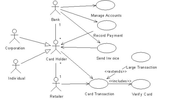
Credit Card Payment System
It's also possible to show relationships (associations and generalizations) between actors in a use case diagram. (Remember, Actor is just a class stereotype with a special icon. Also remember that when UML talks about actors, what they really mean are roles.) Showing relationships between actors is mostly useful for modeling business processes.
Stack Calculator
Apply Function, Apply Trig Function, and Apply Arithmetic Function are abstract use cases:
Other Examples
Sketch use case diagrams for the following systems:
Point of Sale Terminal (POST)
Inventory Control System
Payroll System
Streaming Media Player
Electronic Business
Web Browser
Web Server
Computer
Car
TV
PBX
Call Center
Chat Room
Statistics/Probability Calculator
Financial Calculator
Graphing/Geometry Calculator
Physics Calculator
Integrated Development Environment
Electronic Auction
Patient Monitoring System
ATM
Battlefield Management System
Manufacturing Control System
Embedded flight Control System
Database Management System
Solitaire