Statechart Diagrams
Background
In Statecharts: A Visual Formalism for Complex Systems, David Harel distinguishes between reactive or event-driven systems and transformational systems. A transformational system is simply a function that transforms input data of one type into output data of another type. An event-driven system must react to external events that are to some extent unpredictable. The reaction might include performing certain actions as well as changing the internal state.
A program with a graphical user interface is a good example of an event-driven system, as the program must react to user input events. The timing and type of these events is unpredictable. A server is another good example because the timing and types of client requests can be unpredictable.
Statechart Machines
Harel introduces the concept of a statechart machine as an abstract model of a reactive system. A statechart machine is an example of a finite-state machine. Other similar examples include finite automata, Mealy Machines, Moore Machines, and Petri-Nets. A statechart machine reacts to events such as signals, timeouts, or procedure calls by changing its current state. The statechart machine may also perform certain actions as a result of the state change.
A statechart machine can be described using a statechart diagram. Statechart diagrams are now an official part of the UML specification. A statechart diagram is a directed graph. The nodes of the graph represent states, and the arrows represent transitions between states caused by external events.
Here's an example of a transition:

Semantically this diagram says that if the current state of statechart machine M is STATE1, then when EVENT1 occurs, and if guard1 is true, then actions effect1 and effect2 will be performed and the current state will become STATE2. Upon entering STATE2, M will perform action1 and action2. While the current state is STATE2, M continually performs action3. Upon exiting STATE2, action4 will be performed.
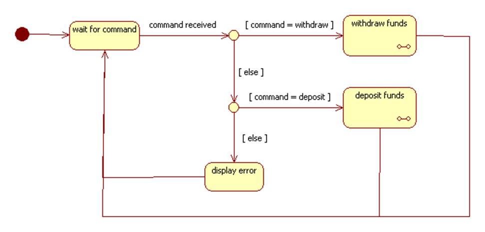
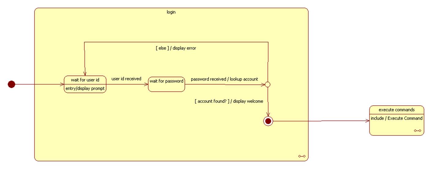
The following example shows part of the lifecycle of a typical command interpreter:

A transition without a trigger, like the one above, usually emanates from a state representing some kind of action. Completion of the action triggers the transition.
Event Types
We call the event that causes the state transition the trigger. There are four types of events that can trigger a state transition:
signal event (the system receives a signal from an external agent)
call event (a system operation is invoked)
timing event (a timneout occurs)
change event (a system property is changed by an external agent)
If an event occurs that is different from EVENT1, or if EVENT1 occurs but guard1 is false, then we may assume that the current state remains STATE1.
Events, guards, effects, and actions are optional.
Start and Final
States
A reactive system has an initial state and one or more final states:

Choice and Junction
Points
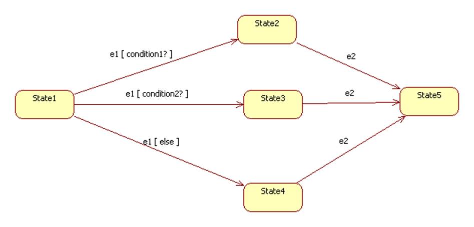
A choice point allows a transition to branch to several different states depending on the value of a guard. A junction point indicates that several states can transition to the same state on a given event:
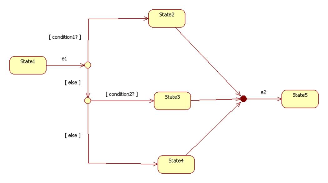
The same machine can be described without choice and junction points:
Example:
Composite States
A composite state (also called a submachine or macro state), is itself a finite state machine consisting of nested micro states. Of course some of these micro states can themselves by composite states:
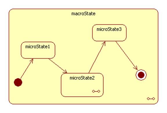
The following example shows two styles of specifying the statechart diagram of a composite state: inline or include a different diagram:
Synchronization
It is possible for an event-driven system to be in two or more states simultaneously. This is common in multi-threaded applications. For example:

Example: E-Store
Checkout

Example: A Server
processing Requests
