Requirements Overview
The requirements activity of software development is often
divided into two sub-activities:
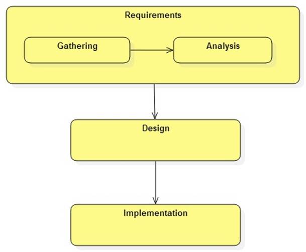
The output of requirements gathering is a requirements
model. This is the input of the analysis activity.
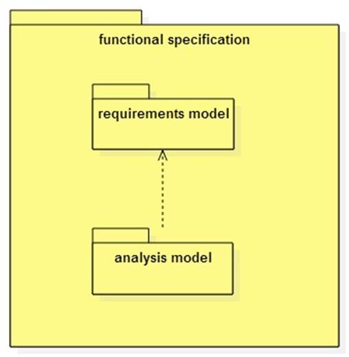
The output of requirements analysis is the analysis model.
Together the analysis and requirements models provide a
model of the system from the user's perspective.
Both models (sometimes collectively referred to as the
functional specification) are the input to the design activity.
The Unified Modeling Language (UML)
UML is a language for describing system models. UML models
often provide one or more views or diagrams. (Often the distinction between
model and view gets blurred, but one model may have many views.)
UML is standardized by the Object
Management Group (OMG).
Developers use computer aided software engineering (CASE)
tools such as StarUML 2
to create models.
The requirements model includes one or more UML use case
models/diagrams.
The analysis model includes one or more UML class
models/diagrams and one or more sequence diagrams.
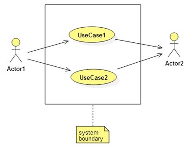
Actors, Use Cases, and Scenarios
Actors are users or systems external to the system being
developed. The system interacts with its actors.
A use case is a system function or goal. Use cases are often
associated with specific actors.
A use case scenario details the interaction between a use
case and its associated actors.
Here is the notation used in a UML use case diagram:
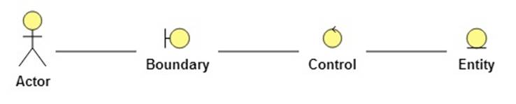
Entities, Controls, and Boundaries
The analysis model consists of entity, control, and boundary
objects usually arranged in concentric rings:
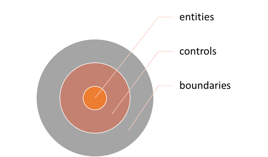
Entities represent objects and events in the application
domain: Employee, Transaction, Plan, Account, etc.
Boundary objects are actor interfaces: GUI, CUI, DAO, etc.
Control objects often correspond to use cases. They
orchestrate the use case scenarios by interacting with boundaries and entities.
UML notation:
Example:
A Simple Account Management System