Requirements
Analysis
The input to the requirements analysis process is the functional specification (aka requirements or use case model).
The output of the requirements analysis process is the analysis model, also called the computation-independent model or CIM:
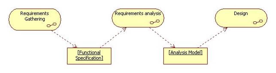
The analysis model describes the system from the user's perspective.
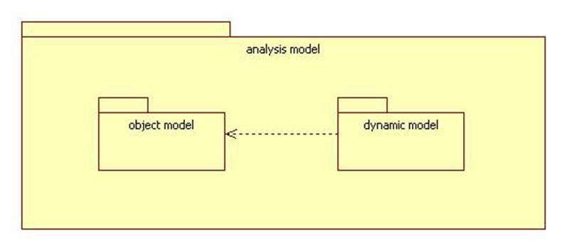
Analysis Model =
Object Model + Dynamic Model
The analysis model contains a class diagram called the object model. The object model describes the structure of the system.
The analysis model also contains sequence diagrams and statechart diagrams associated with control classes in the object model. (A control class implements the logic of one or more use cases.)
These diagrams are collectively called the dynamic model. They describe the internal and external behavior of the system.
The object model consists of entity, control, and boundary objects usually arranged in concentric rings:
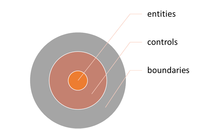
Entities represent objects and events in the application domain: Employee, Transaction, Plan, Account, etc.
Boundary objects are actor interfaces: GUI, CUI, DAO, etc.
Control objects often correspond to use cases. They orchestrate the use case scenarios by interacting with boundaries and entities.
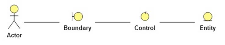
UML notation:
Topics
Entity-Control-Boundary Pattern
The Requirements Analysis Document