Appendix
1:
Object-Oriented Modeling with UML
This appendix introduces important concepts from object-oriented modeling, including UML package, class, object, and interaction diagrams. These will be used throughout the book to describe designs of programs and program fragments prior to their implementations.
Object-Oriented Development
A software project usually involves three participants: the client commissions the software, the developer builds the software, and the user uses the software. These roles may be played by individuals or organizations. In fact, all three roles may be played by the same actor, but it will still be important for the actor to remember which role he is playing at any given moment. Just as a play is divided into carefully scripted acts and scenes, a software project follows a carefully scripted development process. The development process is usually divided into five phases:
Analysis: All three participants create a specification
document that describes the application's requirements as well as the
application domain's important terms, concepts, and relationships.
Design: Using the specification document as a guide, the
developer creates an architectural document that describes the application's
important classes, together with their responsibilities and relationships.
Implementation: The developer implements the classes described in
the architectual document. The developer may need to introduce supporting
classes.
Testing: Of course the developer tests the structure and
function of each class he implements (unit testing). The application must be
tested as a whole, also, first by the developer (integration testing), then by
the users (acceptance testing).
Maintenance: Maintenance involves fixing bugs (corrective
maintenance), porting the application to new platforms (adaptive maintenance),
and adding new features (perfective maintenance).
Iterative-incremental processes mitigate the risk of integration testing by allowing the developer to iterate through these phases many times. Each iteration produces an increment of the specification document, architectural document, and a tested implementation.
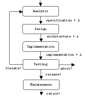
In theory, the developer may be putting final touches on the specification and design documents near the end of the project, while providing implementations of high risk functions near the beginning of the project.
UML
The Universal Modeling Language (UML) is a family of diagram types that appear prominently in specification and architectural documents. UML was developed by Rational Software corporation [WWW-6] and was subsequently chosen by OMG, the Object Management Group [WWW-14], as the "industry standard" object-oriented modeling language. As such, UML replaces or incorporates several competing languages that preceded it.
Although UML describes many types of diagrams, we will only introduce and use a restricted subsets of class, package, object, and interaction (sequence) diagrams. For a more thorough treatment, the interested reader should consult [FOW-1] or any of the dozens of other books on UML that are currently available.
Objects and Classes
A class diagram shows an application's important classes and their relationships. Classes appear in these diagrams as class icons. A class icon is a box labeled with the name of the class it represents. Additional compartments show important attributes and operations:

One or both of these additional compartments may be suppressed when the extra information is unavailable, premature, or unnecessary.
For example, a flight simulation program will probably want to represent airplanes as instances of an airplane class. Suppose we learn that from the flight simulator's point of view, the important attributes of an airplane are its altitude and air speed, and the important operations are takeoff(), fly(), and land(). Here's the corresponding class icon:
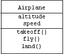
Notice that we have suppressed information about the types, visibility, and initial values of the attributes, as well as the parameters, visibility, and return values of the operations. This is often done when such information is unavailable, unnecessary, or premature.
Of course UML allows us to add this information. For example, it probably makes sense for air speed and altitude to be doubles initialized to zero. (Airplanes are created on the ground and standing still.) Suppose we decide that Airplane may eventually serve as a base class for classes representing special types of airplanes such as military planes and passenger planes. In this case we may want to make altitude and air speed protected instead of private.
Assume we also learn that the takeoff(), fly(), and land() operations are indeed parameterless and have void return values. Of course these operations should be public; however, we find out that they all need to call a supporting function called flaps(), which raises and lowers the wing flaps by a specified integer angle with a default argument of 30 degrees. Because flaps() is only a supporting function, we decide to make it private.
Finally, suppose our unit testing regimen demands that every class provide a public, static operation called test() that returns true if successful and false otherwise. Here is the class icon showing all of this added information:
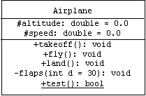
Note that UML indicates visibility using "+" for public, "#" for protected, and "-" for private. Static attributes and operations are underlined. (We use C++ types such as double, int, bool, and void for pre-defined primitive types.)
Some CASE tools (Computer Aided Software Engineering) can generate class declarations from a class diagram containing a sufficient amount of detail. Let's take a moment to consider how an idealized CASE tool might generate a C++ class declaration from our Airplane class icon.
The Airplane class should be declared inside of a header file called airplane.h, which includes some standard header files. The if-not-defined macro, #ifndef/#endif, is used to prevent airplane.h from being included multiple times within the same implementation file, which would result in a compiler error:
/*
* File: airplane.h
* Programmer: Pearce
* Copyright (c): 2000, all rights reserved.
*/
#ifndef AIRPLANE_H
#define AIRPLANE_H
#include <string>
#include <iostream>
using namespace std;
class Airplane
{
// see below
};
#endif
Naturally, C++ will interpret attributes as member variables and operations as member functions. If we zoom in on the class declaration we notice that the public member functions are divided into four groups: constructors and destructor, getters and setters, operations, and the test driver:
class
Airplane
{
public:
// constructors & destructor:
Airplane();
virtual ~Airplane();
// getters & setters:
double getAltitude() const { return altitude; }
void setAltitude(double a) { altitude = a; }
double getSpeed() const { return speed; }
void setSpeed(double s) { speed = s; }
// operations:
void takeoff();
void fly();
void land();
// test driver:
static bool test();
protected:
double altitude;
double speed;
private:
void flaps(int d = 30);
};
The last two groups are self explanatory. A default constructor is needed to initialize the member variables. An empty virtual destructor is a common feature of a base class. For example, assume MilitaryPlane is derived from Airplane:
class
MilitaryPlane: public Airplane { ... };
Deleting an airplane pointer that points to a military plane will automatically call the destructors for both classes:
Airplane*
p = new MilitaryPlane();
// do stuff with p ...
delete p; // calls ~Airplane() and ~MilitaryPlane()
By default, our idealized CASE tool automatically generates member functions that allow us to read (getters) and modify (setters) each member variable. In the case of airplanes, we may want to comment out the setters so that clients can only modify air speed and altitude using the takeoff(), fly(), and land() operations.
Of course our CASE tool also generates an implementation file called airplane.cpp. No class icon contains enough information to specify how its operations should be implemented, so these are left as stubs. Notice, however, that the constructor is implemented; it simply initializes the member variables to their specified initial values.
/*
* File: airplane.cpp
* Programmer: Pearce
* Copyright (c): 2000, all rights reserved.
*/
#include "airplane.h"
Airplane::Airplane()
{
speed = 0.0;
altitude = 0.0;
}
Airplane::~Airplane() {}
void Airplane::takeoff() { /* stub */ }
void Airplane::fly() { /* stub */ }
void Airplane::land() { /* stub */ }
void Airplane::flaps(int d /* = 30 */) { /* stub */ }
bool Airplane::test() { return true; }
Since we are using an idealized CASE tool, it has thoughtfully provided a main() function in a file called main.cpp:
/*
* File: main.cpp
* Programmer: Pearce
* Copyright (c): 2000, all rights reserved.
*/
#include "airplane.h"
int main(int argc, char* argv[])
{
cout << "Airplane::test() = " <<
Airplane::test() << endl;
return 0;
}
Creating files and declarations such as these is often done during early iterations through the implementation phase. After files fill up with implementation details, it can be hard to sort out complex dependencies between files, and simple features such as the default constructor, the virtual destructors, and the getter and setter functions can be forgotten. Also, not all code generators are of the same quality as the one used by our idealized CASE tool, so programmers need to know how to translate class diagrams into declarations by hand.
Object Icons
A UML object diagram shows how an application's important objects are linked together in memory at a moment of time. Objects appear in these diagrams as boxes called object icons. Like a class icon, an object icon is also a labeled box, but there's no danger in confusing the two. The first line of an object icon is the name of the object, if it has one, followed by colon, followed by the name of the class, all underlined. Subsequent lines show each attribute- in the order it was declared- with its current value:
For example, assume two airplanes are created and both take off:
Airplane
a, *b = new Airplane();
a.takeoff();
b->takeoff();
Assume the first has reached an altitude of 30,000 feet and an air speed of 600 mph, while the second has reached an altitude of 27,000 feet and an air speed of 580 mph. Here are the corresponding object icons:
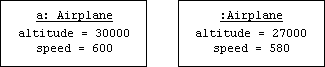
Notice that we show the name of a, but not b. This is because b isn't the name of an object, it's the name of a pointer to an object. In fact, the actual object b points to is anonymous.
Generalization
Object oriented languages allow us to define subclasses. Instances of a subclass inherit the features of the super class. In addition, subclasses can add new features or modify inherited features.
For example, a Polygon class in a graphics program provides member functions for computing area and perimeter. Triangle and Rectangle subclasses might redefine these functions using simpler formulas. Obtuse and acute triangles are instances of subclasses of the Triangle class. In a class diagram we can express the relationship between a subclass and a super class by connecting the class icons with a generalization arrow:
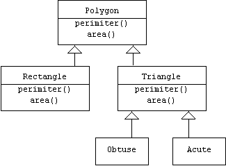
In C++ we can create subclasses using derivation. In this context Polygon is called the base class while Triangle and Rectangle are called derived classes. Of course Triangle is the base class for its derived classes, Obtuse and Acute:
class
Polygon { ... };
class Rectangle: public Polygon { ... };
class Triangle: public Polygon { ... };
class Obtuse: public Triangle { ... };
class Acute: public Triangle { ... };
Java syntax makes the relationship between the two classes clearer by declaring that the features of subclasses extend the features inherited from super-classes:
class
Polygon { ... }
class Rectangle extends Polygon { ... }
class Triangle extends Polygon { ... }
class Obtuse extends Triangle { ... }
cloass Accute extends Triangle { ... }
class Rectangle extends Polygon { ... }
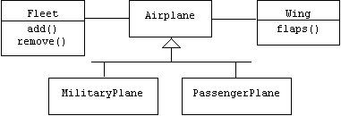
As another example, assume a new release of our flight simulator program will make a distinction between military planes and passenger planes. Of course we will still need to keep track of the altitude and speed of both types of planes, and both types of planes will still need to takeoff, fly, and land. In addition, a military plane can drop bombs and has a Boolean attribute indicating if it is flying at a supersonic speed, while a passenger plane can show movies to its passengers and has an integer attribute indicating how many passengers are on board.
We could replace the Airplane class with PassengerPlane and MilitaryPlane classes, but then we would need to re-implement the takeoff(), fly(), and land() operations. Worse yet, we would need to re-implement these operations twice, once for each new class. Instead, we make the PassengerPlane and MilitaryPlane subclasses of the Airplane class. Now each new class inherits the takeoff(), fly(), and land() operations as well as the altitude and speed attributes from the Airplane super class:

Our class diagram introduces two new features. First, instead of drawing two generalization arrows, we combined them into a single forked arrow. This makes the diagram easier to read and makes it easier to add new subclasses later. Second, we have attached a note to the PassengerPlane class icon. A note is a dog-eared box containing a comment. It has no impact on the implementation, but it can make the class diagram easier to understand.
Assume we create and takeoff in one of each type of airplane:
MilitaryPlane
a;
PassengerPlane b;
a.takeoff();
b.takeoff();
Assume our military plane has reached an altitude of 50,000 feet and a speed of 700 miles per hour, while our passenger plane- which has 80 passengers on board- has reached an altitude of 28,000 feet and a speed of 550 miles per hour. The object diagram depicting this scenario clearly shows the altitude and speed attributes each plane inherits from the Airplane super class:
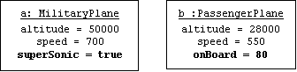
Note that the inherited attributes are listed above the subclass attributes. In fact, this corresponds to the way these objects would be laid out in memory in Java and C++. Thus, instances of MilitaryPlane and PassengerPlane literally are instances of Airplane, but with additional fields hanging off the bottom.
This last observation suggests that it is possible to write generic algorithms that are indifferent to the types of airplanes they process. Such an algorithm can use an airplane pointer to point at both military and passenger planes:
Airplane*
p = 0;
// later ...
p = new PassengerPlane(); // implicit upcast
p->takeoff();
p->fly();
p->land();
delete p;
// and still later ...
p = new MilitaryPlane(); // implicit upcast
p->takeoff();
p->fly();
p->dropBombs(); // this fails
Note that the C++ compiler automatically retypes MilitaryPlane and PassengerPlane pointers to Airplane pointers. This is called an implicit upcast. The term "upcast" indicates that we are retyping a subclass pointer as a super-class pointer. C++ is willing to perform upcasts because a pointer to a subclass instance literally is a pointer to a super-class instance.
However, the compiler rejects the last line:
p->dropBombs();
// this fails
This happens because the compiler doesn't know that p will point to a military plane at the moment this line is executed. Of course we can tell the compiler that this is the case by performing an explicit downcast:
((MilitaryPlane*)p)->dropBombs();
An alternate syntax uses the static_cast<> operator:
(static_cast<MilitaryPlane*>(p))->dropBombs();
But what happens if we are wrong. For example, suppose control arrives at this line of code through some unanticipated route that bypasses the place where p is pointed at a military plane:
Airplane*
p = new PassengerPlane();
p->takeoff();
p->fly();
p->land();
goto Later;
delete p;
p = new MilitaryPlane();
Later:
p->takeoff();
p->fly();
(static_cast<MilitaryPlane*>(p))->dropBombs(); // ???
If we are lucky, the program will simply crash, because p doesn't point at a military airplane. If we are unlucky, then the program won't crash; it will simply produce the wrong behavior. (And so the airplane might crash!)
If we aren't sure what type of plane p will point at, then we can always use a dynamic cast, which returns 0, the null pointer, if the cast doesn't make sense:
MilitaryPlane*
mp = 0;
if (mp = dynamic_cast<MilitaryPlane*>(p))
mp->dropBombs();
else
cout << "wrong type of plane!\n";
Links and Associations
In UML a relationship between two (or more) classes is called an association, and pairs (or tuples) of related objects are called links. For example, an on-line world atlas might represent the relationship "City X is in Country Y" and the relationship "City X is capitol of Country Y" as two associations between the class City and the class Country. In UML an association is a line segment connecting the icons of the related classes:

In this example we have labeled our associations with names and directions. This is the only way to distinguish an association from its inverse association in UML, although in most of our examples the distinction won't be important.
In an object diagram we represent the links "Washington D.C. is capitol of the USA," "Philadelphia is in the USA," and "Washington D.C. is in the USA" with line segments connecting object icons:
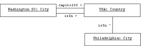
The relationship between links and associations is analogous to the relationship between objects and classes. Sometimes links are referred to as association instances.
Suppose we want to enhance our flight simulator program by allowing users to assemble and command entire fleets of airplanes. In addition, users can customize airplanes by changing the wings, engines, fuselage, and other parts. We begin by adding Fleet and Wing classes to our class diagram. We use associations to represent the relationship between a fleet and its members and the relationship between an airplane and its wings:
Association Roles
The endpoints of an association are called roles. We can add information about an association by attaching navigation arrows, multiplicities, and names to its roles.
Multiplicity
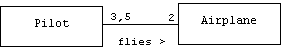
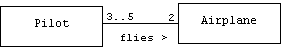
An m-to-n relationship between classes A and B relates a single instance of A to n instances of B, and relates m instances of A to a single instance of B. For example, suppose every airplane in a fleet has exactly three pilots who are authorized to fly it, and suppose every pilot is authorized to fly exactly two planes in the fleet, then the relationship "Pilot X is authorized to fly airplane Y" is a 2-to-3 relationship. In UML we can indicate the multiplicity of a relationship by labeling each role with the multiplicity of its adjacent class:
![]()
If every airplane has 3 or 5 pilots who are authorized to fly it, then we can represent this multiplicity as a sequence:
If every airplane has 3 to 5 pilots who are authorized to fly it, then we can represent this multiplicity as a range:
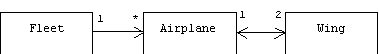
Clearly, every wing is attached to exactly one plane, and every plane has exactly two wings, so the association between Airplane and Wing has 1-to-2 multiplicity. An airplane can only belong to one fleet at a time, but the number of airplanes that belongs to a fleet is zero or more. In UML we use a star to indicate zero or more:
![]()
Navigation
An association between airplanes and wings doesn't necessarily imply that an airplane knows which wings hold it up or that a wing knows which airplane it is attached to. However, an airplane will probably need to send signals to its wings and vice-versa, so it is important that an Airplane object can quickly determine which Wing objects are holding it up, and a Wing object we can quickly determine which Airplane object it is attached to. This property is called navigability. The association between Airplane and Wing has bi-directional navigability. We can represent this by drawing barbed arrow heads at each end of the association.
Clearly an object representing a fleet of planes should know which planes belong to it, but planes move from one fleet to another, and which fleet a plane belongs to will make no difference in how the plane works, so the association between Fleet and Airplane has unidirectional navigability, which UML indicates by drawing an arrowhead only on the Airplane end of the association:
In this book an association without navigation arrows is assumed to have undetermined navigability.
Implementing Associations
In most examples in this book we will represent links using C++ pointers or Java references. (Although links with attributes can be represented by instances of association classes.) For example, here's how our idealized CASE tool interprets the bi-directional, 1-to-2 association between Airplane and Wing:
class
Airplane
{
public:
Airplane();
void setLeftWing(Wing* w) { leftWing = w; }
void setRightWing(Wing* w) { rightWing = w; }
Wing* getLeftWing() const { return leftWing; }
Wing* getRightWing() const { return rightWing; }
// etc.
protected:
Wing *leftWing, *rightWing;
// etc.
};
class
Wing
{
public:
Wing();
Airplane* getAirplane() const { return airplane; }
void setAirplane(Airplane* p) { airplane = p; }
void flaps();
private:
Airplane* airplane;
};
The constructors initialize their pointers to 0:
Airplane::Airplane()
{
leftWing = 0;
rightWing = 0;
speed = altitude = 0.0;
}
Wing::Wing()
{
airplane = 0;
}
Notice that our CASE tool cleverly selected the names leftWing and rightWing for the two Wing pointers encapsulated by an Airplane. Of course a real CASE tool wouldn't know how to differentiate between the two wing pointers, and so would probably choose to store them in a small array:
class
Airplane
{
public:
Airplane() { wing[0] = wing[1] = 0; /* etc. */ }
void setWing(Wing* w, int i) { wing[i] = w; }
Wing* getWing(int i) const { return wing[i]; }
// etc.
private:
Wing* wing[2];
// etc.
};
To convince our CASE tool to generate individually named variables for each Wing pointer we would probably need to show two associations between Airplane and Wing and we would have to name the Wing-side role of each one:

To keep our class diagrams simple, we will avoid drawing multiple associations when a single association will do.
Constraints
Suppose we add an attribute called side to our Wing class that distinguishes between left and right wings:
class
Wing
{
public:
enum Orientation { LEFT, RIGHT };
Orientation getSide() { return side; }
void setSide(Orientation s) { side = s; }
// etc.
private:
Orientation side;
// etc.
};
We can attach constraints to the Wing role of our Airplane-to-Wing associations to require that an airplane's left wing is a left-side wing and its right wing is a right-side wing. A constraint is a Boolean-valued condition bracketed by curly braces. Although OCL, the Object Constraint Language, is a proposed standard language for expressing constraints, we will often simply use Boolean-valued C++ expressions or even informal expressions.
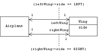
Unlike notes, constraints do impact the implementation, even though the implementation may be ad hoc. For example, we might enforce the orientation constraints on wings in the Airplane's wing setter functions:
void
Airplane::setLeftWing(Wing* w)
{
if (w->side != Wing::LEFT)
throw AirplaneException("bad wing
orientation");
leftWing = w;
w->setAirplane(this);
}
Containers
How will our magic CASE tool represent the association between Fleet and Airplane? Of course the association is unidirectional, so we won't need to make any changes to our Airplane class. But instances of our Fleet class need to hold zero or more Airplane pointers. Placing a static array of Airplane pointers in the Fleet class will impose a maximum size on fleets and will be difficult to manage. Instead, a linked list, dynamic array, or set should be used. Several libraries include implementations of these data structures, including the standard C++ library, which provides vector<T>, list<T>, set<T>, and multiset<T> container templates as well as iterators for accessing their stored elements:
class
Fleet
{
public:
typedef set<Airplane*>::iterator iterator;
void add(Airplane* a) { members.insert(a); }
void rem(Airplane* a) { members.erase(a); }
iterator begin() { return members.begin(); }
iterator end() { return members.end(); }
private:
set<Airplane*> members;
};
Alternatively, we can make Fleet a subclass that privately inherits the features of its set<Airplane*> super-class:
class
Fleet: set<Airplane*>
{
public:
void add(Airplane* a) { insert(a); }
void rem(Airplane* a) { erase(a); }
iterator begin() { return set<Airplane*>::begin(); }
iterator end() { return set<Airplane*>::end(); }
};
The need for private inheritance becomes clear if we want to place restrictions on the type of airplanes that can be added to a fleet. For example, assume all airplanes must pass a quality test before they can be added to a fleet:
class
Fleet: set<Airplane*>
{
public:
void add(Airplane* a) { if (test(a)) insert(a); }
// etc.
private:
bool test(Airplane* a);
};
Private inheritance prevents low quality planes from being added to the fleet through the "back door". For example, assume a particular plane doesn't pass the quality test for a particular fleet:
Fleet
panAm;
Airplane junkHeap;
panAm.add(&junkHeap); // this fails
Thanks to private inheritance, Fleet clients can't call member functions inherited from the set<Airplane*> base class:
panAm.insert(&junkHeap);
// this fails, too!
Composition
In UML we can indicate that instances of class A contain instances of class B rather than pointers to instances of class B by using composition. For example, assume each airplane instance contains two instances of a Date class representing the last time the plane was inspected and the last time the plane was flown. This can be specified in a class diagram by a composition "arrow" connecting the Airplane and Date classes:
![]()
Our idealized code generator generates adds to Date member variables to the Airplane class:
class
Airplane
{
Date inspected, flown;
// etc.
};
Conceptually, composition can be used to represent the relationship between an assembly and its components, but we have to be careful with this. For example, if we represent the relationship between Airplane and Wing using composition:
class
Airplane
{
public:
Wing getLeftWing() { return leftWing; }
Wing getRightWing() { return rightWing; }
// etc.
protected:
Wing leftWing, rightWing;
// etc.
};
then executing the statements:
Airplane
a;
Wing w = a.getLeftWing();
assigns a copy of a.leftWing to w. At this point there are two objects in our application that represent the same wing in the application domain. This may not be a problem if modeling wings isn't an important requirement for our application.
For example, our flight simulator program might have many objects representing the date "January 1, 2000" without causing any confusion. By contrast, if we were developing a calendar program that coordinates appointments, schedules, and important events, then having several objects representing the same date could be a source of confusion. In this case we would probably represent the relationships between events, appointments, and schedules to their appointed date using associations:

In Java associations and compositions are both represented using references:
class
Airplane {
protected Wing leftWing, rightWing; // references
// etc.
}
Although this appears to be composition, leftWing and rightWing are actually references to heap-based Wing objects.
Aggregation
UML also includes a weaker form of composition called aggregation. Conceptually, an aggregation relationship between classes A and B indicate that an instance of A is merely a collection of instances of B. The same instance of B might simultaneously belong to many collections. One of these collections may cease to exist without any effect on its members.
We might have represented the relationship between fleets and airplanes using aggregation, because the same airplane might simultaneously belong to several fleets, and a fleet might disband, but the airplanes that belonged to the fleet still exist. Aggregation is represented in a class diagram by an aggregation "arrow" connecting the aggregate class to its member class:
![]()
Although aggregation may have conceptual value (and even this is debatable), it doesn't seem to suggest anything about implementation beyond what is already suggested using an ordinary association.
Packages
A package is a named set of classes, functions, and sub-packages. Packages are useful for partitioning large programs and libraries into subsystems and sub-libraries. A package diagram shows an application's important packages and their dependencies. Packages appear in these diagrams as labeled folders called package icons. A dependency is a dashed arrow pointing from the client package to the provider package, and indicates that changes to the provider package may force changes to the client package:
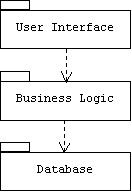
Packages can be implemented in C++ using names spaces:
namespace
Database
{
class Query { ... };
class Table { ... };
// etc.
}
namespace
BusinessLogic
{
using namespace Database;
class Transaction { ... };
class Customer { ... };
// etc.
}
namespace
UserInterface
{
using namespace BusinessLogic;
class ControlPanel { ... };
class MessageDispatcher { ... };
// etc.
}
Java has a similar mechanism.
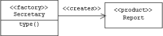
Stereotypes
UML can be extended using stereotypes. A stereotype is an existing UML icon with a stereotype label of the form:
<<stereotype>>
A collaboration is a group of classes that work together to achieve a particular goal. Just as certain data structures can be useful in a wide variety of applications, certain collaborations can be useful in a wide variety of applications. These recurring collaborations will be reintroduced in the next chapter as design patterns.
Although a certain collaboration may have wide applicability, the actual classes that appear in this collaboration may have different names and meanings from one application to the next. In this case stereotypes can be used to indicate the role a class plays within the collaboration. For example, suppose Secretary class has a member function called type() that creates Report objects:
Report*
Secretary::type(...) { return new Report(...); }
In Chapter 3 we will learn that this type of a member function is called a factory method. The class containing the factory method plays the role of a "factory", the return type of the factory method plays the role of a "product", and the association between the factory and product classes is that the factory class creates instances of the product class. We can suggest these associations by simply attaching stereotypes to the icons in our diagram:
Commonly used UML class stereotypes include:
<<powertype>>
= Instances represent subclasses of another class
<<metatype>>
= Instances represent other classes
<<active>>
= Instances own their own thread of control
<<persistent>>
= Instances can be saved to secondary memory
<<control>>
= Instance represent system control objects
<<boundary>>
= Instance represent system interface objects
<<entity>>
= Instances represent application domain entities
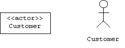
<<actor>>
= Instances represent external systems or users
In some cases a stereotype is so common that it earns its own icon. For example, in UML actors are sometimes represented by stick figures:
Interfaces
When it is time to upgrade or replace a chip in a computer, the old chip is simply popped out of the motherboard, and the new chip is plugged in. It doesn't matter if the new chip and old chip have the same manufacturer or the same internal circuitry, as long as they both "look" the same to the motherboard and the other chips in the computer. The same is true for car, television, and sewing machine components. Open architecture systems and "Pluggable" components allow customers to shop around for cheap, third-party generic components, or expensive, third-party high-performance components.
A software component is an object that is known to its clients only through the interfaces it implements. Often, the client of a component is called a container. If software components are analogous to pluggable computer chips, then containers are analogous to the motherboards that contain and connect these chips. For example, an electronic commerce server might be designed as a container that contains and connects pluggable inventory, billing, and shipping components. A control panel might be implemented as a container that contains and connects pluggable calculator, calendar, and address book components. Java Beans and ActiveX controls are familiar examples of software components.
Interfaces and Components in UML
Modelers can represent interfaces in UML class diagrams using class icons stereotyped as interfaces. The relationship between an interface and a class that realizes or implements it is indicated by a dashed generalization arrow:
Notice that the container doesn't know the type of components it uses. It only knows that its components realize or implement the IComponent interface.
For example, imagine that a pilot flies an aircraft by remote control from inside of a windowless hangar. The pilot holds a controller with three controls labeled: TAKEOFF, FLY, and LAND, but he has no idea what type of aircraft the controller controls. It could be an airplane, a blimp, a helicopter, perhaps it's a space ship. Although this scenario may sound implausible, the pilot's situation is analogous to the situation any container faces: it controls components blindly through interfaces, without knowing the types of the components. Here is the corresponding class diagram:
Notice that all three realizations of the Aircraft interface support additional operations: airplanes can bank, helicopters can hover, and blimps can deflate. However, the pilot doesn't get to call these functions. The pilot only knows about the operations that are specifically declared in the Aircraft interface.
We can create new interfaces from existing interfaces using generalization. For example, the Airliner interface specializes the Aircraft and (Passenger) Carrier interfaces. The PassengerPlane class implements the Airliner interface, which means that it must implement the operations specified in the Aircraft and Carrier interfaces as well. Fortunately, it inherits implementations of the Aircraft interface from its Airplane super-class:
An interface is closely related to the idea of an abstract data type (ADT). In addition to the operator prototypes, an ADT might also specify the pre- and post-conditions of these operators. For example, the pre-condition for the Aircraft interface's takeoff() operator might be that the aircraft's altitude and airspeed are zero, and the post-condition might be that the aircraft's altitude and airspeed are greater than zero.
Interfaces and Components in Java
Java allows programmers to explicitly declare interfaces:
interface Aircraft {
public void takeoff();
public void fly();
public void land();
}
Notice that the interface declaration lacks private and protected members. There are no attributes, and no implementation information is provided.
A Pilot uses an Aircraft reference to control various types of aircraft:
class
Pilot {
private Aircraft myAircraft;
public void fly() {
myAircraft.takeoff();
myAircraft.fly();
myAircraft.land();
}
public void setAircraft(Aircraft a) {
myAircraft = a;
}
// etc.
}
Java also allows programmers to explicitly declare that a class implements an interface:
class
Airplane implements Aircraft {
public void takeoff() { /* Airplane takeoff algorithm */ }
public void fly() { /* Airplane fly algorithm */ }
public void land() { /* Airplane land algorithm */ }
public void bank(int degrees) { /* only airplanes can do this
*/ }
// etc.
}
The following code shows how a pilot flies a blimp and a helicopter:
Pilot
p = new Pilot("Charlie");
p.setAircraft(new Blimp());
p.fly(); // Charlie flies a blimp!
p.setAircraft(new Helicopter());
p.fly(); // now Charlie flies a helicopter!
It is important to realize that Aircraft is an interface, not a class. As such, it cannot be instantiated:
p.setAircraft(new
Aircraft()); // error!
Java also allows programmers to create new interfaces from existing interfaces by extension:
interface
Airliner extends Aircraft, Carrier {
public void serveCocktails();
}
Although a Java class can only extend at most one class (multiple inheritance is forbidden in Java), a Java interface can extend multiple interfaces and a Java class can implement multiple interfaces. A Java class can even extend and implement at the same time:
class
PassengerPlane extends Airplane implements Airliner {
public void add(Passenger p) { ... }
public void rem(Passenger p) { ... }
public void serveCocktails() { ... }
// etc.
}
Interfaces and Components in C++
C++ is much older than Java, so it doesn't allow programmers to explicitly declare interfaces. Instead, we'll have to fake it using classes that only contain public, pure virtual functions:
class
Aircraft // interface
{
public:
virtual void takeoff() = 0;
virtual void fly() = 0;
virtual void land() = 0;
};
A client references a component through an interface typed pointer:
class
Pilot
{
public:
void fly()
{
myAircraft->takeoff();
myAircraft->fly();
myAircraft->land();
}
void setAircraft(Aircraft* a) { myAircraft = a; }
// etc.
private:
Aircraft* myAircraft;
};
Instead of explicitly declaring that a class implements an interface as one does in Java, C++ programmers must declare that a class is derived from an interface. Because all of the interface member functions are pure virtual, this will require the derived class to provide implementations:
class
Airplane: public Aircraft
{
public:
void takeoff() { /* Airplane takeoff algorithm */ }
void fly() { /* Airplane fly algorithm */ }
void land() { /* Airplane land algorithm */ }
void bank(int degrees) { /* only airplanes can do this */ }
// etc.
};
In the following code snippet a pilot first flies a blimp, then a helicopter. Unlike Java, the question of deleting the blimp remains open:
Pilot
p("Charlie");
p.setAircraft(new Blimp());
p.fly(); // Charlie flies a blimp!
p.setAircraft(new Helicopter());
p.fly(); // now Charlie flies a helicopter!
Interfaces and be constructed from existing interfaces through the C++ derived class mechanism, too:
class
Airliner: public Aircraft, public Carrier
{
public:
virtual void serveCocktails() = 0;
};
Here is a C++ implementation of the Airliner interface:
class
PassengerPlane: public Airplane, public Airliner
{
public:
void add(Passenger p) { ... }
void rem(Passenger p) { ... }
void serveCocktails() { ... }
};
Interaction Diagrams
By itself, an object diagram isn't very useful. It becomes much more useful when it shows typical interaction sequences between the objects. An interaction occurs when a client object sends a message or invokes a member function of a server object. The server may or may not return a value to the client.
UML provides two types of interaction diagrams: collaboration diagrams and sequence diagrams. In this book we will use sequence diagrams. At the top of a sequence diagram is a row of object icons. A life line hangs below each icon. If a and b are objects, and if a calls b.fun() at time t, then we would draw a horizontal arrow labeled "fun" that emanates from a's life line at time t, and terminates at b's life line. The exact location of time t on a life line isn't as important as its relative position. Time flows from the top of the diagram to the bottom.
For example, assume a point of sale terminal (POST) records a sale by:
1.
Checking inventory to see if item is in stock
2. Debiting the customer's account.
3. Crediting the retailer's account.
4. Updating inventory.
5. Printing a receipt.
Here is the corresponding sequence diagram:
Problems
Problem A1.1: Modeling Application Domains
An application domain is the real world context of an application: bank, warehouse, space ship, etc. Often, a specification document includes a UML class diagram that represents the application domain's important concepts and relationships as classes and associations respectively. In each of the following problems draw a UML class diagram that models the important concepts and their relationships in the application domain described. You may draw the diagram by hand, with a diagram editor, or by using a CASE tool.
Next, faithfully translate your class diagram into C++ class declarations. Be sure to include all supporting functions implied by your diagram. For example, each member variable requires initialization as well as setter and getter functions (getAAA(), setAAA()). Each container member should provide clients with functions for adding and removing elements as well as traversing the container. Do not invent new member variables or member functions. Each class should be declared in its own header file and should have its own source file (even if it's empty).
A scenario description follows each domain description. Draw an object diagram that instantiates your class diagram and models the scenario. Implement a main() function in main.cpp so that it creates the objects and links in your object diagram. Insert diagnostic messages in main() to prove your program compiles and runs.
Problem A1.1.1
Domain:
A course is taught in a school by a teacher. There are two types of courses:
seminars and lectures. Any number of students may take a course, but a student
may take no more than five courses per term. Teachers teach from two to four
courses per term.
Scenario:
Bill Jones and Sue Smith are students at Cambridge University, where they both
take a Physics seminar taught by Professor Newton.
Problem A1.1.2
Domain:
A warehouse has any number of aisles, an aisle has any number of bins, a bin
has any number of boxes, and a box contains any number of items.
Scenario:
The AA Warehouse stores whiskey in bin 3 of aisle 6, beer in bin 6 of aisle 3,
and wine in bin 2 of aisle 6.
Problem A1.1.3
Domain:
A play has many characters. A play occurs on a stage and has three acts. Each
act has three scenes. A character may be played by many different actors, and
an actor may play different characters.
Scenario:
Hamlet is being performed at the Globe theater. Mel Gibson plays Hamlet, and
Drew Barrymore plays Ophelia.
Problem A1.1.4
Domain:
A tennis tournament has many matches. Each match is between two players and
consists of six or seven games. Each game consists of six or seven sets, and
each set consists of five or more points.
Scenario:
Venus Williams is playing her sister, Serena, in the championship match at the
US Open. Venus wins the first game of the match: 5-0, 4-2, 2-4, 5-1, and 4-2.
Problem A1.1.5
Domain:
A
C++ program is a sequence of declarations:
PROGRAM
::= DECLARATION ...
Besides
declarations, there are two other types of C++ statements: expressions and
control structures:
STATEMENT
::= DECLARATION | EXPRESSION | CONTROL
There
are four types of control structures: conditional (if-else, switch), iterative
(for, do-while, and while), jump (break, continue, goto, return), and block.
CONTROL
::= CONDITIONAL | ITERATIVE | JUMP | BLOCK
A
block is a sequence of statements between curly braces:
BLOCK
::= { STATEMENT ... }
An
if-else statement consists of an expression (the condition), and one or two
statements (the consequent and the alternative):
IF
::= if (EXPRESSION) STATEMENT [else STATEMENT]
A
while or do-while statement consists of a condition (the loop condition) and a
statement (the iterate):
WHILE
::= while (EXPRESSION) STATEMENT
DO ::= do STATEMENT while (EXPRESSION);
Scenario:
if
(x < y) x = 0; else x = y;
Problem A1.1.6
Domain:
A hospital has many patients. Each patient has one doctor, although a doctor
may have several patients. Tests are performed on each patient resulting in
many measurements that must be recorded in a data base. In some cases the
measurements can be complicated data structures. Examples of measurements
include blood pressure, temperature, and pulse. It's important to know the time
of a measurement.
Scenario:
At 3:00 PM on July 4, in St. Yak's hospital, Dr. Gump measures patient Smith's
blood pressure (120/80) and temperature (99).
Problem A1.1.7: Transaction Processing
Domain:
A transaction processor creates and commits transactions. Each transaction
represents the action of withdrawing funds from on account and depositing them
in another. Besides a balance and a password, each account is associated with
an owner. An owner has a name and a PIN number.
Scenario:
Bill Smith transfers $50 from his savings account into his checking account.
Problem A1.2: The UML Meta Model
While instances of a power type represent subclasses, instances of a meta class represent classes in general. In fact, meta classes can be used to represent any UML element.
Draw a UML class diagram that represents the important concepts and relationships of UML based on the following summary:
Two
classes may be related by a dependency. There are two types of dependencies:
generalization and association. Each endpoint of an association can have a
name, multiplicity, and a navigation arrow. Composition and aggregation are two
special types of associations.
Your diagram might be useful in a specification for a CASE tool.
Problem A1.3: Recursive Containers
A container contains components. Components of a recursive container may themselves by containers. In each of the following problems, draw a class diagram representing the domain. Translate your diagram into C++ class declarations. Prove your declarations work by writing a simple test harness.
Problem A1.3.1
A
folder may contains files. These files may be documents, applications, or other
folders.
Problem A1.3.2
A
tree has two types of nodes: parents and leafs. A parent node has one or more
nodes below it (called the child nodes). A child node may be a leaf or a
parent. A leaf node has no children.
Problem A1.4: Reverse Engineering
Assume the following C++ class declarations have been made:
class
A { public: virtual void f() = 0; ... };
class B: public A { A* a; ... };
class C: public A { A* a; ... };
class D { list<A*> as; ... }; // list<> is an STL container
class E: public B, public C { D* d; ... };
Draw a class diagram showing the relationship between A, B, C, D, and E.