Sequential Circuits
State Machines
A state machine is an abstract input-output device.

However, the output of a state machine depends on its input AND its current internal state, which may change as a result.
In other words, given the same input on two different occasions, the output may not be the same because the internal state may have been different on the second occasion.
In other words, the device "remembers" past inputs and this memory, along with input, affects future outputs.
State Machine Diagrams
We can represent the internals of a state machine using a state machine diagram. Here's an example of a MOD-4 counter:

In this example the states are represented by bubbles. There are four states: Q=0, Q=1, Q=2, and Q=3. A state may also contain a do-action. This action is performed repeatedly while the machine is in this state. In our example the do-action for each state is to output a number. In state Q=0, the output is O=0, etc.
An arrow connecting state A to state B represents a transition from A to B. The arrow is labeled by the event that caused the transition, usually an input event.
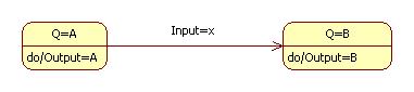
In our example if the MOD-4 counter is in state Q=0 and receives the input I=1. This causes it to transition to state Q=1 and start outputting O=1. As long as the device receives input I=0, it remains in state Q=1 and continues to output O=1. However, the next time the device receives input I=1, it transitions to state Q=2 and begins to output O=2.
Externally, this may seem puzzling. At one point in time input 1 caused output 1, but later, input 1 causes output 2.
Memory
The MOD-4 counter is an example of a device with memory. In this case the memory capacity is 2 bits. Why?
Sequential Circuits
We can implement a state machine using logic gates, but this time we add an ingredient not found in stateless combinatorial circuits: feedback!
Flip-Flops
A flip-flop is a one-bit memory. A one-byte register can be implements as 8 flip-flops, and a 1 GB RAM can be implemented as 230 one-byte registers.
There are many types of flip-flops. For a complete discussion, see:
http://wearcam.org/ece385/lectureflipflops/flipflops/#Contents
The S-R Flip-Flop
The Set-Reset flip-flop has two inputs, S and R, and two outputs, Q and Q':

The state of a flip-flop is the output, Q. Normally, Q' will
be the complement of Q. Thus, a flip-flop is a 1-bit memory.
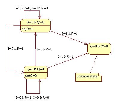
Here's a state diagram showing the influence of S and R on Q and Q'.
Note that the output produced when S = R = 0 depends on the previous values of Q and Q'.
We can implement a flip-flop with a pair of cross-coupled NOR gates:
The flip-flop is in a stable state if Q and Q' have different values.
In "storage mode" S = R = 0 and feedback maintains the values of Q and Q'.
If S = 1 and R = 0, then Q = 1 and Q' = 0. In other words, the state is set to 1.
If S = 0 and R = 1, then Q = 0 and Q' = 1. In other words, the state is reset to 0.
If S = 1 and R = 1, then Q = Q' = 0. In this case we say that the flip-flop is in an unstable state.
Project
Build a MOD-4 counter using Logisim.
Hint: use two flip-flops.