Analysis Model for InCase
Client: Acme Inc.
Developer: CyberSystems.com
Author: Jon Pearce
Introduction
See the InCase Functional Specification for an overview of InCase.
The Analysis Model
InCase will provide a graphical user interface with menus and control panels that allow developers to easily create, edit, open, and save system models and their components.
Here is an overview:
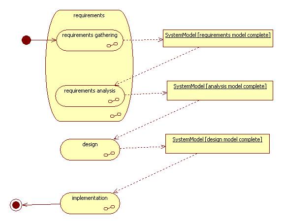
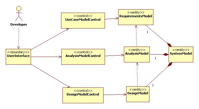 \
\
The System Model and its Components
The system model is the central focus of InCase. It's three major components are the requirements, analysis, and design sub-models. Both the requirements and analysis models describe the system from the user's view, while the design model describes the system from the developer's view. (In a sense, we can think of the requirements model as the user's view on the user's view, while the analysis model is the developer's view on the user's view.)
These sub-models are developed (perhaps iteratively) during different phases of the software development lifecycle.
Boundaries and Controls
The main purpose of this analysis model is to describe the software development models (i.e., the InCase entities). Discussion of boundaries and controls—all of which are straight forward—will be suppressed.
Entities
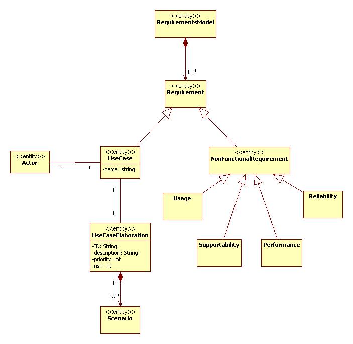
The Requirements Model
The requirements model contains a set of requirements.
Requirements can be functional or non-functional. Non-functional requirements are called use cases.
Each use case has an elaboration containing one or more scenarios. A use case may have associated actors.
The Analysis Model
An analysis model contains objects representing actor interfaces (boundaries), business objects (entities), and use case processors (controls).
Each control has an associated state machine representing its internal dynamics, and one or more interactions (sequence diagrams) representing its interactions with other objects in the model. These interactions can be viewed as realizations of the use case scenarios from the requirements model.
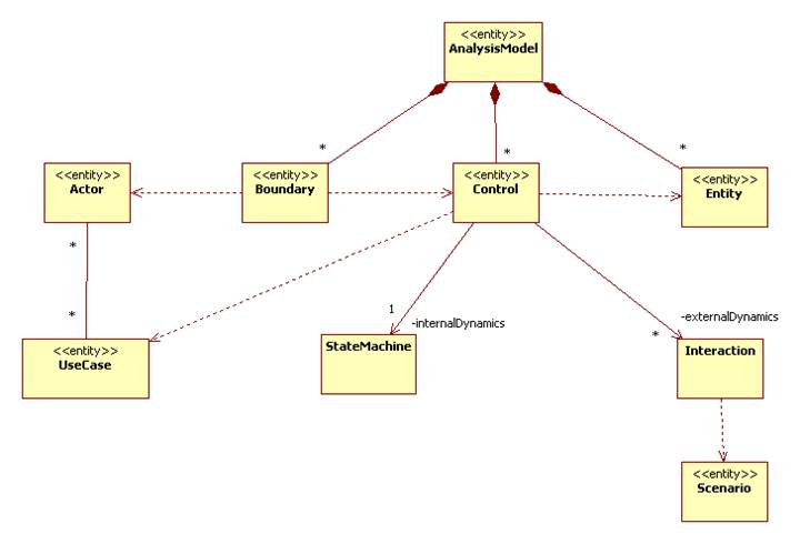
Note: The InCase analysis model given above is an instance of this diagram!
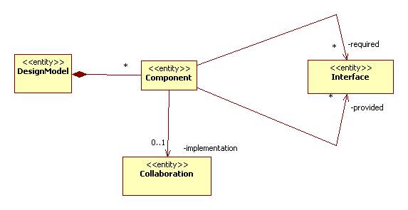
The Design Model
The design model is a collection of components.
Externally, each component is specified by a set of required interfaces and a set of provided interfaces.
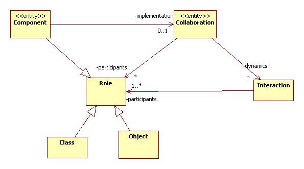
Internally, each component is implemented by a collaboration.
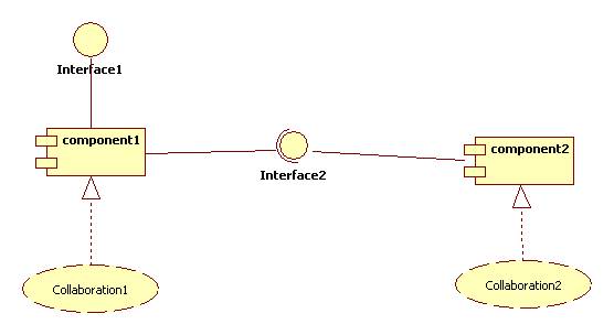
For example, the following component diagram can be viewed as an instance of a design model:
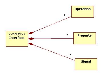
An interface consists of a set of operations, properties, and signals:
A collaboration consists of roles and interactions between the roles. Classes, objects, and sub-components may be substituted for roles:
Revision History
|
Revision |
Revised by |
Date |
|
1.0 |
|
|
|
1.1 |
|
|
|
2.0 |
|
|
|
|
|
|
|
|
|
|
|
|
|
|
|
|
|
|
|
|
|
|
References
Object Oriented Analysis Lectures