5 Graphics Programming 2.0
5.1 Overview
This chapter presents more advanced concepts of graphics programming in MFC by extending the three applications presented in Chapter 4. Version 2.0 of Screen Test introduces fonts and mapping modes. Version 2.0 of Paint introduces double buffering, and version 2.0 of Draw introduces composite shapes.
5.2 Screen Test 2.0
Version 1.0 of Screen Test demonstrated the difference between the view window and the underlying canvas. Recall that OnDraw() actually draws on a bitmap we think of as a virtual canvas, while the view window affords us a view of the portion of the canvas that it currently hovers over. Graphics can have fixed positions relative to the coordinate system of the canvas, or their positions can be relative to the current position of the view rectangle:
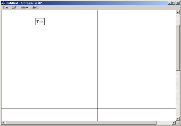
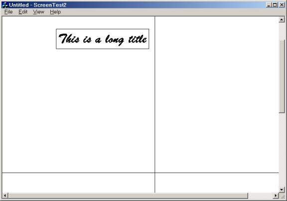
Users can see other portions of the underlying canvas either by enlarging the view window or by using scroll bars to move other parts of the canvas under the view window. Version 2.0 of Screen Test provides the view window with horizontal and vertical scroll bars for this purpose. The user can use these scroll bars to inspect fixed horizontal and vertical axes that intersect in the middle of the canvas. A boxed title appears at a fixed position in the second quadrant of the axes:
Here's a screen shot of Screen Test 2.0:
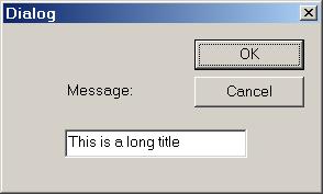
Selecting the [Edit]/[Text] menu item displays a dialog box that allows users to change the text of the title:
Selecting the [Edit]/[Font] menu item displays a Font Dialog that allows users to change the font, size, and style of the title:
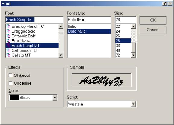
Notice that the box surrounding the title automatically expands to circumscribe the new title:
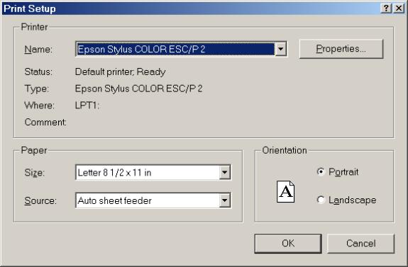
As always, selecting the [File]/[Print Setup ...] menu item allows users to specify the current printer and the size of paper being used:
Selecting the [File]/[Print Preview] menu item displays the entire canvas— either one or two pages at a time— according to the selected paper size:
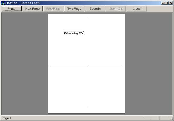
Of course selecting the [File]/[Print ...] menu item sends the canvas to the current printer one page at a time.
Setting up the printer, previewing, and printing are functions provided by the MFC framework. No extra work is required of the programmer. What is unusual about version 2.0 of Screen Test is that the printed page exactly matches the canvas. The canvas measures 8.5 inches by 11 inches, exactly the same size as standard letter size paper; the x-axis stretches from the left center of the page to the right center, just as it does on the canvas; the y-axis stretches from the top center of the page to the bottom center, just as it does on the canvas; and if the size of the title box is .5 inches by 2 inches on the canvas, then it will have the same dimensions on the printed page. In short, Screen Test 2.0 is a WYSIWYG application— What You See (on the screen) Is What You Get (when you print).
Unfortunately, getting canvas graphics to match page graphics does require some work from the programmer. This is because the default unit of measurement for both the printer and the canvas is a pixel. However, the printer's definition of a pixel seldom matches the screen's definition of a pixel. To get page and canvas graphics to match, the programmer must abandon the pixel as the unit of measure and work with inches or centimeters, instead.
5.2.1 Implementation
Like version 1.0, Screen Test 2.0 is a single document application. In fact, there is no Screen test data to speak of; its document is empty. We will only need to edit the view class. The easiest way to provide scroll bars is to specify CScrollView, a subclass of CView, as the base class of the Screen Test 2.0 view class.
Step 1:
i. Use the MFC App Wizard to create a single document application called "ScreenTest2".
ii. In the [Step 6 of 6] dialog, choose CScrollView as the base class of CScreenTest2View.
Next, we add three member variables to the view class. The first variable holds the text of the title, the second describes the font used to display the title, and the third stores the size of the canvas.
Step 2: Add private member variables to CScreenTest2View called msg, font, and canvasSize. The msg variable is of type CString, and represents the label that will appear in the view. The font variable is of type CFont and represents the font used to print msg. The canvasSize variable is of type CSize, and represents the size of the canvas upon which msg will be written.
Here is a partial listing of the CScreenTest2View declaration:
class CScreenTest2View : public CScrollView
{
// etc.
private:
CString msg; // message to be
displayed
CFont font; // font used to display
msg
CSize canvasSize; // size of canvas
};
Of course the member variables must be initialized in the constructor.
Step 3: Initialize msg, font, and canvas in the constructor.
Here is a complete listing of the constructor:
CScreenTest2View::CScreenTest2View()
{
msg = "Title";
font.CreatePointFont(120,
"Courier");
canvasSize.cx = 850;
canvasSize.cy = 1100;
}
Our unit of measurement will be .01 inches instead of the pixel. We want canvas size to equal page size; because standard letter size paper is 8.5 inches by 11 inches, we set the canvas size to be 850 by 1100 hundredths of an inch. The initial font will be 12 point Courier.
5.2.1.1 Fonts
A font consists of a character set, typeface, size, and style. The character set of a font is the collection of glyphs (letters, digits, punctuation marks, and other printable symbols) that can be printed. Typeface refers to how the glyphs are drawn. For example, a serif is a horizontal stroke drawn at the bottom of a downward stroke in certain typefaces:
this font uses the serif
this font is sans-serif
Typeface also determines if the width of a glyph is fixed (mono-spaced) or if it depends on the letter (proportional):
This is a mono-spaced font
This is a proportional font
Typefaces are divided into families such as Modern (mono-space with or without serifs), Roman (proportional with serifs), and Swiss (proportional, san-serif). Specific typefaces are identified by their names: Courier, Arial, Times, New York, Windings, etc.
The style of a font refers to its slant and line weight of a glyph:
this font style
is bold and italicized
Size refers to the number of points from the bottom of a lower case "g" to the top of an uppercase "M". A point is approximately 1/72 inches.
This is 22 point font
Of course a font must be installed on a computer before an application can display its glyphs.
Fonts are represented in MFC by instances of the CFont class. These objects are device context drawing tools, just like brushes and pens:
After a CFont object is created, it must be associated with an installed font using one of the initialization functions:
class CFont: public CGDIObject
{
public:
// initialization functions:
BOOL CreateFontIndirect(...);
BOOL CreateFont(...);
BOOL CreatePointFont(...);
BOOL CreatePointFontIndirect(...);
// etc.
};
Our constructor initializes the font member variable using the CreatePointFont() function:
font.CreatePointFont(120, "Courier");
This function allows us to specify the size (in tenths of a point) and name of the typeface.
5.2.1.2 OnInitialUpdate()
When a view is first displayed, the framework calls the view's OnInitialUpdate() function. The default implementation of this function simply calls OnUpdate(). OnInitialUpdate() is a good place to do one-time initializations of the corresponding system-level view object. (Recall that when the application view object is created and its constructor is called, the corresponding system-level view object may not yet exist.)
In our case, we want to set the size of the canvas and the unit of measurement. Both of these jobs can be done by calling the SetScrollSizes() member function of the CScroll class:
void CScrollView::SetScrollSizes(
int nMapMode, CSize sizeTotal, ...);
The size of the canvas is determined by the canvasSize member variable. The unit of measurement, .01 inches, is called "low resolution English mapping mode" or MM_LOENGLISH.
Step 4: Set the size and mapping mode of the canvas in OnInitialUpdate().
Here is a complete listing of OnInitialUpdate():
void CScreenTest2View::OnInitialUpdate()
{
CScrollView::OnInitialUpdate();
SetScrollSizes(MM_LOENGLISH,
canvasSize);
}
5.2.1.3 Mapping Modes
An important part of two-dimensional graphics programming is understanding the relationships between three coordinate systems: world coordinates, logical coordinates, and device coordinates.
The world is the rectangular region of the application domain that we are interested in modeling: a map of India, a circuit diagram for a new computer chip, the graph of a function. A point in the world is represented as a pair of real numbers that specify the x and y coordinates of the point relative to a world coordinate system. The units of this coordinate system might be anything: miles, dollars, temperatures, etc.
The canvas is a rectangle representing the page or pages upon which we wish to render the world. (Microsoft uses the term "page" instead of "canvas". This can be a little confusing when a document consists of multiple pages.) A canvas has a built-in coordinate system called device coordinates. In device coordinates the origin is located at the upper left corner of the canvas, the positive x-axis runs across the top of the canvas, the positive y-axis runs backwards down the left edge of the canvas, and units are measured in pixels. Of course the size of a pixel depends on the resolution of the computer's screen. A point on the canvas is represented as a pair of integers that specify the x and y coordinates of the point relative to the device coordinate system.
To overcome the fact that different graphics devices have different sizes of pixels, a canvas is also equipped with a logical coordinate system. The default logical coordinate system is called text coordinates, text mapping mode, or MM_TEXT. Text coordinates are almost exactly the same as device coordinates. The only difference is that the origin of text coordinates doesn't have to be mapped to the top left corner of the canvas (although this is where it is initially mapped to). In general, we can specify that an arbitrary point in logical coordinates should be mapped to the top left corner of the canvas by using the device context's SetWindowOrg() function. For example, if pDC is a CDC pointer, then the call:
pDC->SetWindowOrg(CPoint(100, 100));
specifies that the logical point (100, 100) should be mapped to the device point (0, 0).
Of course text coordinates still use the device pixel as the unit of measurement. Fortunately, we can change the logical coordinates of the canvas using the device context's SetMapMode() function. Besides MM_TEXT, Windows provides five other logical coordinate systems. In each of these systems, the origin is initially mapped to the top left corner of the canvas, the positive x-axis runs across the top of the canvas, the negative y‑axis runs along the left side of the canvas, and the unit or measurement is device independent:
mapping mode units
MM_LOENGLISH .01 inches
MM_HIENGLISH .001 inches
MM_LOMETRIC .1 mm
MM_HIMETRIC .01 mm
MM_TWIPS 1/1440 inches
For example, if pDC is a CDC pointer, we can change the logical coordinates to MM_LOENGLISH with the call:
pDC->SetMapMode(MM_LOENGLISH);
We need to be careful. If we set the size and position of a rectangle using device coordinates, then draw the rectangle on the canvas:
CRect myBox(0, 5, 5, 3);
pDC->Rectangle(myBox);
we see nothing at all. This is because the canvas is a subset of the fourth quadrant of the MM_LOENGLISH coordinate system:
To fix this problem we must change the sign of the y-coordinates:
CRect myBox(0, -5, 5, -3);
In addition to fixed-scale logical coordinate systems, Windows also provides two variable scale systems: MM_ISOTROPIC and MM_ANISOTROPIC. These coordinate systems allow programmers to create images that automatically change size when the view is resized. If the isotropic mode is used, the scale along the x and y axes are the same. If the anisotropic mode is used, then the scale along the x and y axes can be different.
Drawing a real world object on a canvas can be viewed as a mathematical transformation that maps the world onto the canvas, taking points in world coordinates into points in the logical coordinates of the canvas.
Displaying the canvas in the view window can also be viewed as a mathematical transformation of the canvas into the view rectangle. In this case logical coordinates of the canvas are mapped to device coordinates, then points outside the client rectangle of the view are clipped. In fact, every device context provides a member function called LPtoDP() that transforms points in logical coordinates to corresponding points in device coordinates. The inverse transformation is called DPtoLP(). If we call the transformation that takes world points to logical points WPtoLP(), and its inverse LPtoWP(), then we can represent the rendering process as follows:
OnDraw()
The OnDraw() function performs three tasks:
1. Draw the message box.
2. Calculate the center point of each edge of the canvas.
3. Draw the axes by connecting the center points.
Calculating the center points is straight forward, except we must remember that in the MM_LOENGLISH mapping mode y-coordinates are negative:
CPoint leftCenter(0, -canvasSize.cy/2);
CPoint rightCenter(canvasSize.cx, -canvasSize.cy/2);
CPoint topCenter(canvasSize.cx/2, 0);
CPoint bottomCenter(canvasSize.cx/2, -canvasSize.cy);
We draw the axes by connecting the top and bottom center points and by connecting the left and right center points:
pDC->MoveTo(leftCenter);
pDC->LineTo(rightCenter);
pDC->MoveTo(topCenter);
pDC->LineTo(bottomCenter);
Drawing the title box begins by selecting the font into the device context. When the task is complete, the original font will be restored:
CFont* oldFont = pDC->SelectObject(&font);
// draw title box
pDC->SelectObject(oldFont);
The upper left corner of the rectangle that circumscribes the title is fixed at the point x = 150, y = -150. The bottom right corner of the rectangle is determined by the length and height of the message. This depends on the number of characters in the message and also the device context's selected font. The size of the message can be computed by calling the device context's GetTextExtent() member function. To provide a small margin for the title, we position the bottom right corner of the box an extra tenth of an inch beyond the end of the message. The message itself is displayed beginning one twentieth of an inch from the upper left corner of the box:
CSize msgSize = pDC->GetTextExtent(msg);
CRect fixed(150, -150, 160 + msgSize.cx, -160 - msgSize.cy);
pDC->Rectangle(&fixed);
pDC->TextOut(155, -155, msg);
Step 5: Implement OnDraw() so that it displays the message in a box and draws perpendicular and horizontal axes that intersect in the middle of the canvas.
Here's a complete listing of OnDraw():
void CScreenTest2View::OnDraw(CDC* pDC)
{
CScreenTest2Doc* pDoc = GetDocument();
ASSERT_VALID(pDoc);
// draw message box:
CFont* oldFont =
pDC->SelectObject(&font);
CSize msgSize = pDC->GetTextExtent(msg);
CRect fixed(150, -150, 160 +
msgSize.cx, -160 - msgSize.cy);
pDC->Rectangle(&fixed);
pDC->TextOut(155, -155, msg);
pDC->SelectObject(oldFont);
// calculate center points:
CPoint leftCenter (0,
-canvasSize.cy/2);
CPoint rightCenter (canvasSize.cx,
-canvasSize.cy/2);
CPoint topCenter(canvasSize.cx/2, 0);
CPoint bottomCenter(canvasSize.cx/2,
-canvasSize.cy);
// draw axes:
pDC->MoveTo(leftCenter);
pDC->LineTo(rightCenter);
pDC->MoveTo(topCenter);
pDC->LineTo(bottomCenter);
}
5.2.1.4 Create Menus
Next, we use the Menu Editor to add two new entries to the bottom of the [Edit] menu: [Text] and [Font].
Step 6: Use the Menu Editor to add [Font] and [Text] items to the bottom of the [Edit]menu on the main frame's menu bar.
Be sure to add tool tips and shortcut keys for these items. Specify their identifiers to be ID_EDIT_FONT and ID_EDIT_TEXT, respectively.
5.2.1.5 Message Handlers
Surprisingly, a CScrollView-derived view doesn't automatically redraw itself when it is scrolled. The programmer must do this.
Step 7: Use the Class Wizard to add a handler to the view for the OnScroll message. This handler simply invalidates the view.
BOOL CScreenTest2View::OnScroll(
UINT nScrollCode, UINT nPos, BOOL
bDoScroll)
{
Invalidate();
return CScrollView::OnScroll(nScrollCode,
nPos, bDoScroll);
}
Fortunately, MFC provides a pre-defined font dialog wrapper class called CFontDialog. If the dialog is dismissed by clicking the [OK] button, the dialog's GetCurrentFont() function can be called to get a LOGFONT object— a Win32 data structure used to describe the attributes of a font. After deleting the font currently associated with the font member variable, we can associate a new font based on the LOGFONT description using the CreateFontIndirect() function:
BOOL CFont::CreateFontIndirect(const LOGFONT* lpLogFont);
Step 8: Use Class Wizard to add a handler to the view for the ID_EDIT_FONT message. This handler displays a Font Dialog, updates the font member variable, then invalidates the view.
Here's a complete listing of the menu handler:
void CScreenTest2View::OnEditFont()
{
CFontDialog cfd;
if (cfd.DoModal() == IDOK)
{
LOGFONT lf;
cfd.GetCurrentFont(&lf);
font.DeleteObject();
font.CreateFontIndirect(&lf);
}
Invalidate();
}
We complete the application by designing a message text box that will be displayed when the user selects the [Edit]/[Text] menu item:

Step 9:
i. Use the Dialog Editor to create the Message Dialog shown above.
ii. Summon the Class Wizard from the short cut menu of the Message Dialog in the Dialog Editor. This will automatically create a CDialog-derived wrapper class called CMsgDialog
iii. Use the [Class Wizard]/[Member Variables] dialog to add a CString member variable called m_msg to the CMsgDialog class. this variable corresponds to the Edit Box.
The handler for [Edit]/[Text] creates, initializes, then displays a message dialog. When DoModal() returns, the msg member variable is updated and the view is invalidated.
Step 10: Use the Class Wizard to add a handler for the ID_EDIT_TEXT message to the view. This handler displays a CMsgDialog, transfers the dialog's m_msg variable to the view's msg variable, then invalidates the view.
Here's a listing of the handler:
void CScreenTest2View::OnEditText()
{
CMsgDialog md;
md.m_msg = msg;
md.DoModal();
msg = md.m_msg;
Invalidate();
}
Step 11: Build and Test the application.
5.3 Paint 2.0
Paint 2.0 adds three features to Paint 1.0. First it's a multiple document application. This means users can work on several paintings at the same time. It also means that the user can have several views of a single painting. As the user drags the mouse across the canvas of one view, trails of paint can be seen in the other views.
Second, dragging the mouse across a Paint 2.0 canvas doesn't leave a path of dots. Instead, each sampled mouse position is connected to the previously sampled position by a solid line.
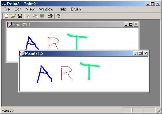
Finally, Paint 2.0 fixes the problem of inadvertently erasing work. When a paint 2.0 window is uncovered, the users work will still be visible.
5.3.1 Designing the Paint Program
Our paint program employs an interesting design called double buffering. As the user drags the mouse across the canvas of a view, it will appear as if the mouse cursor is leaving a trail of paint in its path. In fact, the mouse cursor isn't painting on the view's canvas at all! Instead, it is leaving a trail of paint on a canvas managed by the view's associated document. As the mouse moves, the document's canvas is modified, and all subscribing views are notified. Upon notification, each view invalidates its window, which forces a call to the view's OnDraw() function. The OnDraw() function transfers the image painted on the document's canvas onto the blank canvas that accompanies its device context parameter.
5.3.2 Implementing the Paint 2.0 Program
Our implementation strategy has four phases. In the first phase we create a reusable memory device context class. In phase two we create a document that encapsulates a memory DC. In phase three we implement the view class, which includes a mouse movement handler. In phase four we provide menus and menu handlers that allow users to modify the brush width and color. As always, we begin by asking the MFC App Wizard to generate the framework of our application.
Step 1: Use the MFC App Wizard to create a multi-document application called "Paint2".
5.3.2.1 Double Buffering
Double buffering is a technique that employs two canvases (i.e. buffers). One canvas is associated with a window (i.e., resides in the memory segment used by the monitor), while the other lives in a memory segment used by the application. The application draws or paints on the second canvas, then uses an efficient bit transfer operation to copy the second canvas onto the first canvas. The idea is that drawing or painting on a canvas can take time. If the painting is being done directly on a view window's canvas, then the constant refreshing of the view (as well as other open views) can create annoying screen flicker. By contrast, the bit transfer operation is so fast that the user hardly notices the refresh operations. Double buffering is an alternative strategy to invalidating rectangles. (Although the two can be combined.)
5.3.2.2 Memory Device Context
Given the usefulness of double buffering, it's surprising that MFC doesn't provide a type of device context that can be used as a memory buffer. (CClientDC, CMetaFileDC, CPaintDC, and CWindowDC are the MFC classes derived from CDC.) Creating a memory DC turns out to be non-trivial. Our version is a simplification of a memory device context given in [Rucker]. Readers should consult this work for a more detailed treatment of these objects.
Step 2:
i. Use the [Insert]/[New Class ...] menu to insert a new class called MemoryDC into the Paint project. In the [New Class] dialog box select "generic" from the [Class Type] pull-down list. (CDC doesn't appear on the list of possible base classes for a new MFC class!)
ii. Ordinarily, this dialog would generate files called MemoryDC.h and MemoryDC.cpp, but we use the dialog's [Change] button to change the names of these files to memdc.h and memdc.cpp, respectively.
iii. To make it easy to reuse memdc.h and memdc.cpp in other projects, we remove all of the pre-processor directives in these files and replace them with our own.
The memdc.h file should have the following form:
#ifndef MEMDC_H
#define MEMDC_H
#include <afx.h>
class MemoryDC
{
...
};
#endif
Our memdc.cpp file begins with the directives:
#include "stdafx.h"
#include "memdc.h"
Of course our MemoryDC class must be derived from MFC's CDC class. We will also provide MemoryDC with a screen-size rectangle.
Step 3:
i. By editing memdc.h, make CDC the base class for MemoryDC.
ii. Add a protected member variable called screen of type CRect.
Here's a partial listing:
class MemoryDC : public
CDC
{
protected:
CRect screen; // size of screen
// etc.
};
5.3.2.2.1 Creating Bitmaps
Instances of the CDC class can be used to represent any type of graphics output device: printers, plotters, and monitors, but a MemoryDC specifically represents the monitor. The MemoryDC constructor needs to replace the bitmap (i.e., the canvas) inherited from the CDC base class— the monitor's bitmap— with a new bitmap that lives in memory and is compatible with the size and depth of the monitor.
Step 4: Implement a MemoryDC constructor that calculates the size of the screen, then creates a new, blank screen compatible bitmap for itself.
We use the global GetSystemMetrics() function to calculate the largest possible canvas that will fit on the screen. A separate initialization function is used to create a compatible bitmap, and a separate clear function is used to paint the bitmap white.
MemoryDC::MemoryDC()
{
int screenWidth =
GetSystemMetrics(SM_CXFULLSCREEN) -
GetSystemMetrics(SM_CXFRAME) -
GetSystemMetrics(SM_CXVSCROLL);
int screenHeight =
GetSystemMetrics(SM_CYFULLSCREEN) -
GetSystemMetrics(SM_CYFRAME) -
GetSystemMetrics(SM_CYMENU) -
GetSystemMetrics(SM_CYHSCROLL);
screen.SetRect(0, 0, screenWidth,
screenHeight);
Init(); // create a new bitmap
Clear(); // erase new bitmap
}
The Init() function creates a screen-compatible bitmap. This requires four steps. First, we must create a temporary device context representing the monitor's screen. Second, we create a screen-size bitmap for this device context. Third, we make the memory device context compatible with this screen device context, and fourth, we use the SelectObject() function to replace the bitmap of the memory device context by the bitmap of the screen device context.
Step 5: Create and implement a protected member function named Init(). This function creates a screen-compatible bitmap, then uses the SelectObject() function to replace its given bitmap with the new one.
We can initialize a device context so that it represents a particular graphics device by calling its CreateDC() function. For example, if dc is a device context, then the call:
dc.CreateDC("DISPLAY", NULL, NULL, NULL);
initializes the attributes of dc so they match the attributes of the monitor.
Unfortunately, this device context comes equipped with a tiny one-by-one monochrome bitmap, regardless of the capabilities of the actual monitor. This is because the "real" bitmap of this device context is the monitor's bitmap. We can initialize a bitmap to have the same size and depth as the monitor by calling the CreateCompatibleBitmap() function. For example, if bm is a CBitmap instance, dc is our display device context, and width and height are the dimensions of the screen, then the call:
bm.CreateCompatibleBitmap(&dc, width, height);
initializes bm so that it has the same height, width, and depth as the display.
Finally, we can initialize one device context to be compatible with another by calling another variant of the CreateCompatibleDC() member function. If dc is the screen device context created earlier, and mDC is a second device context, then we can make mDC into a screen-compatible device context with the call:
mDC.CreateCompatibleDC(&dc);
Here's the complete implementation of Init():
void MemoryDC::Init()
{
// make a CDC for the display:
CDC displayDC;
displayDC.CreateDC("DISPLAY",
NULL, NULL, NULL);
// allocate screen size & depth
bitmap for display:
CBitmap canvas;
canvas.CreateCompatibleBitmap(
&displayDC, screen.Width(),
screen.Height());
// make memory DC like the displayDC:
CreateCompatibleDC(&displayDC);
// install bitmap:
CBitmap* oldBitmap =
SelectObject(&canvas);
oldBitmap->DeleteObject();
}
5.3.2.2.2 Block Transfer Operations
Every CDC comes equipped with member functions that paint directly on the CDC's bitmap:
class CDC: public CObject
{
public:
COLORREF SetPixel(int x, int y,
COLORREF c);
COLORREF GetPixel(int x, int y);
BOOL PatBlt(int x, int y, int w, int h,
int rop);
BOOL BitBlt(int x, int y, int w, int h,
CDC* sdc, int sx, int sy, int rop);
BOOL StretchBlt(int x, int y, int w,
int h,
CDC* sdc, int sx, int sy, int sw,
int sh, int rop);
// etc.
};
The purpose of the first two functions should be obvious. The next three functions have a "Blt" suffix, which is pronounced "blit" and stands for "BLock Transfer". A block transfer combines the bitmap in a destination device context with a bitmap in a source device context:
destDC.bitmap = sourceDC.bitmap ROP destDC.bitmap
Each pixel in the destination bitmap is replaced by the result of combining that pixel with the corresponding pixel in the source bitmap. The method of combination is called a raster operation (ROP). If a pixel is a single bit, then raster operations are just the Boolean operations (or, xor, nor, and, nand, etc.). If a pixel is a binary word, then raster operations are bitwise Boolean operations.
The CDC block transfers allow users to operate on rectangles within the source and destination bitmaps. The first four parameters specify the top left corner, height, and width of the destination bitmap rectangle. The last parameter is a binary word that specifies a raster operation to be used. Naturally, MFC has pre-defined the most common raster operations.
In the case of PatBlt() there is no source bitmap. Instead, a pre-defined pattern of bits is being transferred to the destination bitmap. For example, the WHITENESS raster operation makes every pixel in the destination bitmap white. We use this to implement our Clear() function.
Step 6: Create and implement a member function named Clear(). Clear() uses the PatBlt() function inherited from CDC to erase the entire canvas.
void MemoryDC::Clear()
{
PatBlt(0, 0, screen.Width(),
screen.Height(), WHITENESS);
}
The BitBlt() and StretchBlt() functions combine a destination rectangle with a source rectangle according to a specified raster operation. In the case of BitBlt() the source rectangle is assumed to be the same size as the destination rectangle. The StretchBlt() function allows these rectangles to be different sizes, and automatically performs the necessary stretching or compressing.
We provide two member functions called CopyTo(). Both call the BitBlt() function of a specified device context, specifying the implicit parameter (i.e., a memory device context) as the source. In our paint application the destination device context will be the parameter passed to CPaint2View's OnDraw() function. This function will call the CopyTo() function of the document's device context.
Step 7:
i. Create and implement a member function named CopyTo(). CopyTo() uses the BitBlt() function inherited from CDC to transfer its bitmap onto the bitmap of another device context.
ii. Add an inline variant of CopyTo() that passes the screen rectangle to the first version of CopyTo().
Here's a complete listing of the first CopyTo() function:
void MemoryDC::CopyTo(CDC *pDC, const CRect &rect)
{
pDC->BitBlt(rect.left, rect.top,
rect.Width(), rect.Height(),
this, rect.left, rect.top,
SRCCOPY);
}
Here's the complete declaration of MemoryDC. This shows the inline implementation of the second CopyTo() function:
class MemoryDC : public
CDC
{
public:
MemoryDC();
virtual ~MemoryDC();
void Clear(); // clears the bitmap
void CopyTo(CDC *pDC, const CRect
&rect);
void CopyTo(CDC *pDC) { CopyTo(pDC,
screen); }
protected:
CRect screen; // same size as screen
void Init(); // creates a screen bitmap
};
5.3.2.3 The Paint Document
The CPaint2Doc class encapsulates a memory DC, and provides an AddPoint() function the moves the memory DC's pen from its current position to the specified point using a specified pen. The color and width of the line drawn by the pen are determined by two additional member variables: color and brushWidth. Naturally, setters are provided for these variables. These variables determine the attributes of a virtual pen object that is also encapsulated by the document.
Step 8:
i. Add a public member variable called mDC of type MemoryDC to CPaint2Doc.
ii. Add a private member variable called color of type COLORREF and a private member variable called brushWidth of type int.
iii. Add private member variables called oldPen and newPen of type CPen*.
Here's a partial listing of CPaint2Doc showing these declarations:
class CPaint2Doc : public CDocument
{
public:
MemoryDC mDC;
// etc.
private:
COLORREF color;
int brushWidth;
CPen *oldPen, *newPen;
};
Of course we will need to include memdc.h at the top of Paint2Doc.h:
#include "memdc.h"
5.3.2.3.1 Construction and Destruction
Step 9:
i. Implement the default constructor to initialize the member variables.
ii. Implement the destructor so that it exchanges the old and new pens.
The default constructor initializes brushWidth and color. Next, the new pen is created using the CPen constructor. We specify the style of the pen's line to be solid, the width of the line to be brushWidth, and the color of the line to be color. Finally, the new pen replaces the old pen in the mDC, the document's memory device context:
CPaint2Doc::CPaint2Doc()
{
color = RGB(0, 0, 255);
brushWidth = 3;
newPen = new CPen(PS_SOLID, brushWidth,
color);
oldPen = mDC.SelectObject(newPen);
}
The destructor return's the encapsulated memory DC's original pen just before it is destroyed:
CPaint2Doc::~CPaint2Doc()
{
mDC.SelectObject(oldPen);
}
5.3.2.3.2 AddPoint()
As the mouse is dragged across a canvas, the mouse handler sends the sampled mouse locations to the document's AddPoint() function. This function simply moves the document's pen to the specified point in document's memory device context.
Step 10: Create and implement a member function called AddPoint(). AddPoint() expects a CPoint as input (the mouse position) and returns nothing, but moves mDC's pen using the LineTo() function. Because AddPoint() modifies the document's memory context, it must set the modified flag and update all views.
Here's a listing:
void CPaint2Doc::AddPoint(CPoint p)
{
mDC.LineTo(p.x, p.y);
SetModifiedFlag(TRUE);
UpdateAllViews(NULL);
}
5.3.2.4 The Paint2 View
The CPaint2View class has controller and presentation responsibilities. The OnDraw() function will display the document's memory DC. The view will also respond to mouse motion.
Step 11: Use the Class Wizard to add a handler function for the WM_MOUSEMOVE message to the CPaint2View class.
Recall that the WM_MOUSEMOVE message is sent to an application every time the operating system samples the mouse position and notices that it has changed from the previous sampling. In addition, a binary word indicating the state of the mouse and keyboard at the time of the sample is also sent. Our handler function determines if the left mouse button was down at the sampling time (indicating that the mouse was being dragged) by forming the bitwise conjunction of the flags parameter with the "left button down" mask. If the left mouse button is down, the sampled point is sent to the document's AddPoint() function:
void CPaint2View::OnMouseMove(UINT nFlags, CPoint point)
{
if (nFlags & MK_LBUTTON)
{
CPaint2Doc* pDoc = GetDocument();
pDoc->AddPoint(point);
}
CScrollView::OnMouseMove(nFlags,
point);
}
Of course AddPoint() will call UpdateAllViews(), which will call the OnUpdate() function of each view.
Step 12: Use the Class Wizard to add an OnUpdate() function to CPaint2View. This function simply invalidates the entire view window.
Recall that the Invalidate() function has a parameter called bErase that determines if the background of the invalid region should be erased before it is repainted:
void CWnd::Invalidate(BOOL bErase = TRUE);
Normally, we want the background to be erased, which is why the default argument is set to TRUE. In the case of a paint program, however, erasing the background is unnecessary and will re-introduce the screen flashing we are working hard to eliminate.
void CPaint2View::OnUpdate(
CView* pSender, LPARAM lHint, CObject*
pHint)
{
Invalidate(FALSE);
}
Invalidating the view will indirectly call the view's OnDraw() function, which must copy the document's memory DC onto the device context passed to it by OnPaint().
Step 13:
i. Implement OnDraw(). OnDraw() simply calls the CopyTo() function of the document's memory DC.
ii. Build and test the application.
Here's a listing for OnDraw():
void CPaint2View::OnDraw(CDC* pDC)
{
CPaint2Doc* pDoc = GetDocument();
ASSERT_VALID(pDoc);
pDoc->mDC.CopyTo(pDC); // pDC = mDC
}
5.3.2.5 Menu Handlers
As in version 1.0, Paint 2.0 provides a [Brush] menu that allows users to change the color and width of the paint trail created by the mouse. The main difference between the version 1.0 and 2.0 menu handlers is their location. In version 1,0 the [Brush] menu handlers were located in the view class, CPaint1View. This won't work for a multi-document application. There may be multiple open views, yet all must respond to changes in the brush. The solution employed by version 2.0 is to place the [Brush]menu handlers in the document class.
Step 14:
i. Use the Menu Editor to create a [Brush] menu containing two items: [Color] and [Brush Width]. This menu should be added to the IDR_PAINT2TYPE menu. (What goes wrong if we add it to the IDR_MAINFRAME window?)
ii. Check the [Pop-up] box in the [General] sheet of the properties dialog page of the [Brush Width] menu. This creates a pop-up menu that appears when the mouse is dragged over the [Brush Width] menu.
iii. Add three items to this pop-up menu: [Small]. [Medium], and [Large].
iv. Use the Class Wizard to add handler functions for these menu items in the CPaint2Doc class. In the case of the brush width items, also add handlers for the UPDATE_COMMAND_UI messages that are sent just before the menu item is displayed.
v. Implement these handlers.
vi. Build and test the application.
The handler for the [Brush]/[Color] menu item uses MFC's CColorDialog class to get the user's color selection. Next, a new pen is constructed. This pen becomes the memory device context's new pen. The old pen is deleted.
void CPaint2Doc::OnBrushColor()
{
// get color selection:
CColorDialog cd;
cd.DoModal();
color = cd.GetColor();
// create new pen:
CPen* p = newPen;
newPen = new CPen(PS_SOLID, brushWidth,
color);
mDC.SelectObject(newPen);
delete p;
}
The handlers for the brush width menus are all similar. When the COMMAND message is sent, the brushWidth member variable is set to one of three pre-defined constants. A new pen is costructed and selected into the memory context. The old pen is deleted. For example:
void CPaint2Doc::OnBrushPenwidthLarge()
{
brushWidth = LARGE_BRUSH;
// create new pen:
CPen* p = newPen;
newPen = new CPen(PS_SOLID, brushWidth,
color);
mDC.SelectObject(newPen);
delete p;
}
Of course we will need to define these constants at the top of PaintDoc.h:
#define SMALL_BRUSH 1
#define MEDIUM_BRUSH 3
#define LARGE_BRUSH 5
Recall that the application receives the UPDATE_COMMAND_UI message just before the menu item is displayed. The handler for this message receives a pointer to the CCmdUI object that will be used to determine the appearance of this menu item. We can use this object to specify that a menu item should be checked if the current brush width already matches the brush width determined by the menu item:
void CPaint2Doc::OnUpdateBrushPenwidthLarge(CCmdUI* pCmdUI)
{
if (brushWidth == LARGE_BRUSH)
pCmdUI->SetCheck(1); // check
item
else
pCmdUI->SetCheck(0); // uncheck
item
}
5.3.2.6 Changing the Cursor
As a final touch, we should change the cursor when the mouse is being dragged. A cursor is a resource, just like menus, toolbars, and dialogs. We can create a new cursor resource using the Cursor Editor (select [Cursor] from the [Insert]/[Resource ...] menu) or we can use a pre-defined cursor resource. Changing the cursor is easy if we use a pre-defined cursor.
Step 15: Add a member variable to the CPaint2View class called cursor of type HCURSOR.
HCURSOR cursor;
Step 16:
i. Initialize this variable in the OnInitialUpdate() function by calling the global LoadCursor() function.
ii. Set the cursor in the OnMouseMove() function by calling the global SetCursor() function.
iii. Build and test the application.
If we use a pre-defined cursor, then the first argument passed to LoadCursor is always NULL, while the second argument is the resource identifier of the desired cursor. In our case we will use the four-pointed compass called IDC_SIZEALL:
cursor = LoadCursor(NULL, IDC_SIZEALL);
Here's our new implementation of OnMouseMove():
void CPaint2View::OnMouseMove(UINT nFlags, CPoint point)
{
if (nFlags & MK_LBUTTON)
{
SetCursor(cursor);
CPaint2Doc* pDoc = GetDocument();
pDoc->AddPoint(point);
}
CScrollView::OnMouseMove(nFlags,
point);
}
5.4 Draw 2.0
Version 1.0 of the Draw program was nearly useless. A more useful version would allow users to position any number of shapes on the canvas. Each one could be individually selected and edited. An adequate collection of simple shapes would be provided as well as composite shapes, which are formed when the user groups several selected shapes together.
Version 2.0 of Draw fulfills these requirements. (At least it will after several enhancements described in the problems section.) Draw 2.0 is a multiple document, multiple view application. Using a special [Shape] menu users can create and edit boxes, ovals, and labels (i.e., boxes containing text). These shapes can be positioned on the canvas using the mouse:
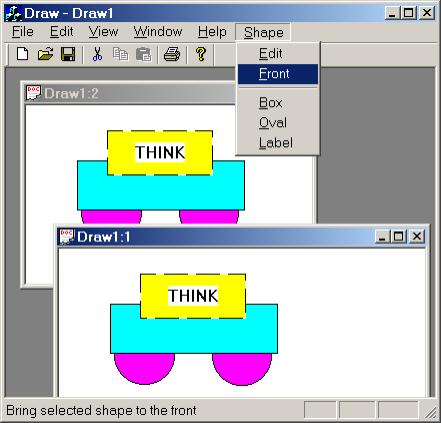
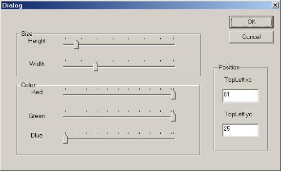
Users can select shapes by clicking in them with the mouse. The border of the selected shape is dashed. The selected shape can be dragged using the mouse. The menu selections [Shape]/[Front], [Edit]/[Cut], and [Shape]/[Edit] apply to the selected shape. The [Shape]/[Front] menu selection moves the selected shape to the top of a stack of superimposed shapes. The [Edit]/[Cut] selection deletes the selected shape. The [Shape]/[Edit] selection displays the modal version of the [Shape Edit] dialog box:
5.4.1 Designing The Draw Program
We use the Composite Design Pattern from Section 2.5 to represent shapes. All shapes are instances of classes derived from an abstract Shape base class. There are two types of shapes: simple shapes such as ellipses, labels, points, polygons, and line segments, and composite shapes. A composite shape is a collection of shapes that have been grouped together and are now treated as a single shape. Moving, drawing, and resizing operations applied to a composite shape are automatically applied to each member of the composite. Of course a member of a composite shape may itself be a composite shape. Thus, a shape has a logical, tree-like structure in which parent nodes are composite shapes and leaf nodes are simple shapes.
Our current design defines four shape classes: Oval, Box, Label, and Composite. These are derived from a slightly modified version of the Shape class from version 1.0. From this base class each shape inherits information about its size, color, and position. In addition, each Shape subclass inherits a virtual Draw() function which it must redefine, because when a composite shape is drawn, each component will be asked to draw itself.
The model maintained by a version 2.0 document is a composite shape. The document also maintains a pointer named current to one of the model's component shapes. As its name suggests, this pointer points to the currently selected shape. All move, resize, and delete operations are applied to this shape.
5.4.2 Implementation
The implementation of version 2.0 of the Draw program begins by making a copy of the version 1.0 Draw program.[1] This will spare us the pain of recreating the [Shape] dialog box. Four phases follow. In phase one we extend the Shape class into a hierarchy of shape classes corresponding to different types of shapes, including composite shapes. In phase two we modify the version 1.0 document class so that its model is a composite shape. In phase three we make some minor modifications in the version 1.0 view class that allow users to select components of the model with the mouse. In the final phase we provide the application with a menu for creating and modifying model components.
Step 1:
i. Open the Draw Project from the previous chapter.
ii. Select [Clean] from the [Project] menu. This will delete all reproducible files in the project, making it smaller.
iii. Close the project.
Step 2:
i. Duplicate the folder containing the Draw workspace.
ii. Name the new folder Draw 2.0.
iii. To make sure everything was copied, build and test Draw 2.0.
5.4.2.1 The Shape Hierarchy
Logically, a composite shape can be viewed as a tree in which parent nodes are composite shapes, leaf nodes are simple shapes, and child nodes are the component shapes (both composites and simples) grouped together by their parent node.
It will be important to be able to navigate through this tree, both from parent to child and from child to parent. We accomplish this by providing every instance of the Shape class with a pointer to its composite parent, and by providing every composite with a list of pointers to its children. If a shape has no parent, then the parent pointer will be 0.
In version 2.0 the document model is a composite shape and users have the ability to select individual components of the model with the mouse. Subsequent operations are applied to the selected component. The user can tell which component has been selected, because its border is dashed rather than solid. To implement this feature, we add a Boolean flag to each shape. When a shape is selected, its selected flag will be set to true.
Step 3:
i. Add a Composite pointer member variable to the Shape class named parent. Initialize this to 0 in the Shape constructor. Add a getter and setter for parent.
ii. Since the Composite class hasn't yet been defined, add a forward reference to the Composite class just above the declaration of Shape in Shape.h
iii. Add a Boolean flag called selected to the Shape class. This variable should be initialized to false in the constructor. Add a getter and setter for this variable.
iv. Remove the body of the Draw() function. This function now has an empty body.
Here's a partial listing for Shape. The boldface sections were added in Step 3. The rest of the code is from version 1.0 of Draw:
class Composite; // forward reference
class Shape : public CRect
{
public:
Shape(int h = 50, int w = 100, int xc =
0, int yc = 0)
: CRect(xc, yc, xc + w, yc + h)
{
color = RGB(255, 0, 255);
NormalizeRect();
parent = 0; // orphaned at birth
selected = FALSE;
}
Composite* GetParent() { return
parent; }
void SetParent(Composite* s) { parent =
s; }
BOOL GetSelected() { return selected; }
void SetSelected(BOOL flag = TRUE) {
selected = flag; }
// etc.
protected:
virtual void Draw(CDC* pDC) { /* no
op */ };
COLORREF color;
Composite* parent;
BOOL selected;
};
5.4.2.2 Plotting Shapes
Recall that the Plot() function selected an appropriately colored brush into its device context parameter, passed this parameter to the Draw() function, then deselected and discarded the brush after Draw() terminated.
The new version of Plot() is essentially the same. The only modification is that we create a dashed pen to draw the border of the shape if the shape is selected. This will help users identify which shape on the screen has been selected for an operation.
Step 4: Plot() should select a dashed pen to draw the border of the selected shape.
Here's a complete listing of Plot(). The new code is in boldface.
void Shape::Plot(CDC* pDC)
{
CBrush *newBrush, *oldBrush;
newBrush = new CBrush(color);
oldBrush =
pDC->SelectObject(newBrush);
CPen *newPen, *oldPen;
COLORREF black = RGB(0, 0, 0);
if (selected)
newPen = new CPen(PS_DASH, 1,
black);
else
newPen = new CPen(PS_SOLID, 1,
black);
oldPen = pDC->SelectObject(newPen);
Draw(pDC); // implemented by derived
classes
pDC->SelectObject(oldPen);
delete newPen;
pDC->SelectObject(oldBrush);
delete newBrush;
}
5.4.2.3 Implementing Atomic Shapes
The Draw() function in the Shape class does nothing at all.[2] It is a virtual function that will be redefined in classes derived from Shape. The atomic shapes redefine Draw() to draw simple rectangles, ovals, and text.
Step 5: Add Oval, Box, and label classes to the bottom of Shape.h
The Oval and Box classes are derived from Shape and simply redefine the Draw() function to draw an ellipse or rectangle, respectively, in the device context parameter:
class Oval: public Shape
{
void Draw(CDC* pDC) {
pDC->Ellipse(this); }
};
class Box: public Shape
{
void Draw(CDC* pDC) {
pDC->Rectangle(this); }
};
The Label class has a CString member variable that holds the text of the label. The Draw() function draws this text in the device context:
class Label: public Shape
{
public:
Label(CString t = "THINK") {
text = t; }
void SetText(CString t) { text = t; }
private:
CString text;
void Draw(CDC* pDC)
{
pDC->Rectangle(this);
pDC->DrawText(text, this,
DT_SINGLELINE | DT_VCENTER |
DT_CENTER);
}
};
5.4.2.4 Implementing Composite Shapes
The main feature of the Composite class, besides the fact that it's derived from the Shape class, is that it maintains a list of shape pointers.
Step 6:
i. Include the MFC templates just before the declaration at the bottom of Shape.h
ii. Below this use typedef to introduce ShapeList as a short name for a CList of Shape pointers.
iii. Below this declare a Composite class derived from the Shape class. Equip this class with a private member variable called children of type ShapeList.
iv. Declare member functions for adding and removing children.
v. Declare member functions for moving, and drawing the children.
vi. Declare a function for selecting a child given a CPoint.
Here's a listing of the Composite class:
#include <afxtempl.h>
typedef CList<Shape*, Shape*> ShapeList;
class Composite: public Shape
{
public:
Shape* Select(CPoint p); // find child
containing p
void Add(Shape* s); // add a child
void Remove(Shape* s); // remove a child
void Draw(CDC* pDC); // draw all children
void Move(CPoint p); // move all children
void Move(Shape* s, CPoint p); // move
a child
private:
ShapeList children;
};
We implement the Composite member functions in shape.cpp.
Step 7: Implement Composite Select() function. This function returns a pointer to the first child containing a given point, p.
The Select() function traverses the shape list using a position iterator, pos, that's set to the head of the list. For each child we ask if point p is in the child's bounding box. The search ends when we get a positive answer or when we reach the end of the list. Here's a complete listing:
Shape* Composite::Select(CPoint p)
{
POSITION pos =
children.GetHeadPosition();
Shape* result = 0;
BOOL found = FALSE;
while(pos != NULL && !found)
{
result = children.GetNext(pos);
found = result->PtInRect(p);
}
if (found)
return result;
else
return 0;
}
Step 8: Implement the Composite Add() function.
The Add() function of a composite, c, adds a given shape, s, to the rear of its list of children, then sets the parent of s to be c. Finally, the new bounding box of c is the union of the bounding box of s and the old bounding box of c:
void Composite::Add(Shape* s)
{
children.AddTail(s);
s->SetParent(this); // adopt
UnionRect(this, s);
}
Step 9: Implement the Composite Remove() function.
Removing a child s from a composite, c, reverses the adding procedure. The parent of s is set to 0, the new bounding rectangle of c is the old bounding box minus the bounding box of s, and s is removed from the children list:
void Composite::Remove(Shape* s)
{
POSITION pos = children.Find(s);
if (pos != NULL)
{
s->SetParent(0);
SubtractRect(this, s);
children.RemoveAt(pos);
}
}
Step 10: Implement the Composite Draw() function.
The Composite Draw() function simply passes its device context parameter to the Plot function of each child:
void Composite::Draw(CDC* pDC)
{
POSITION pos =
children.GetHeadPosition();
Shape* next = 0;
while(pos != NULL)
{
next = children.GetNext(pos);
next->Plot(pDC);
}
}
Step 11: Implement both of the Composite Move() functions.
There are two Composite Move() functions. The first one moves a component shape, s, to a given point, p. The only problem is that the old bounding rectangle of s must be subtracted from the bounding rectangle of the parent before the move. After the move, the new bounding rectangle of s must be added back to the bounding rectangle of its parent:
void Composite::Move(Shape* s, CPoint p)
{
if (children.Find(s) != NULL)
{
SubtractRect(this, s);
s->Move(p);
UnionRect(this, s);
}
}
The other Move() function moves all of the children to a given point:
void Composite::Move(CPoint p)
{
POSITION pos =
children.GetHeadPosition();
Shape* next = 0;
while(pos != NULL)
{
next = children.GetNext(pos);
Move(next, p);
}
}
Step 12: Build and test.
5.4.2.5 Modifying the Document
In version 2.0 of Draw, the document's model is a composite shape. A shape pointer called current points to the selected component of the model. The document will also need Add(), Remove(), and Select() functions. These simply call the corresponding model functions. The version 2.0 document also encapsulates a CRect member. Model components that intersect with this member are invalid and will need to be redrawn.
Step 13:
i. In CDrawDoc change the type of the model from Shape to Composite.
ii. Add a private Shape pointer called current, which is initialized to 0 in the constructor.
iii. Add a private CRect member variable called invalidRect. Also add a getter function for this variable.
iv. Add declarations of Add(), Remove(), and Select() member functions.
v. Change the return type of GetModel from Shape to Composite&. (Unfortunately, no copy constructor is available for ShapeList, so no copy constructor is generated for Composite, and therefore Composites can't be passed or returned by value, but they can be passed and returned by reference. )
Here is a partial listing of the CDrawDoc class. Modifications are shown in boldface:
class CDrawDoc : public CDocument
{
public:
CDrawDoc() { current = 0; }
void Add(Shape* s);
void Remove(); // remove current
BOOL Select(CPoint p);
CRect GetInvalidRect() { return
invalidRect; }
Composite& GetModel() { return
model; }
// etc.
private:
Composite model;
Shape* current; // selected shape
CRect invalidRect;
// etc.
};
Step 14:
i. Implement the Add() function so that it adds shape s to a model and sets it to be the current shape.
ii. Implement the Remove() function so that it removes the current shape from the model's children.
Of course the model, a composite shape, already provides Add() and Remove() functions. The corresponding document functions call these functions. After the document's Add() function calls its model's Add() function, it sets the current shape to be the newly added shape, sets the modified flag, then updates all of the views:
void CDrawDoc::Add(Shape* s)
{
model.Add(s);
if (current)
current->SetSelected(FALSE);
current = s;
current->SetSelected(TRUE);
SetModifiedFlag(TRUE);
UpdateAllViews(NULL);
}
The Remove() function asks the model to remove the current shape. After this the current shape pointer is set to 0. Once again, the modified flag is set and the views are updated:
void CDrawDoc::Remove()
{
if (current)
{
current->SetSelected(FALSE);
model.Remove(current);
delete current;
current = 0;
SetModifiedFlag(TRUE);
UpdateAllViews(NULL);
}
}
Step 15: Modify the Select() function. First note that in version 2.0 this function returns a Boolean rather than void. Select() locates the model component containing a given point, p, then sets this to be the current shape. If no shape is selected, Select() returns FALSE.
The document's Select() function is passed a point p from the mouse button. This point is passed to the model's Select() function, which either returns the null pointer or a pointer to the selected component. This pointer becomes the document's current shape. The mouse offset is the distance from the point p to the top left corner of the selected shape. This will be needed for dragging the shape:
BOOL CDrawDoc::Select(CPoint p)
{
if (current)
current->SetSelected(FALSE);
current = model.Select(p);
if (current)
{
current->SetSelected(TRUE);
mouseOffset = p -
current->TopLeft();
}
SetModifiedFlag(TRUE);
UpdateAllViews(NULL);
return (current != 0); // anything
selected?
}
Step 16: Modify the document's Move() function so that it sets the invalid rectangle field to be the union of the old position of the current shape together with its new position.
Unlike version 1.0 of the Draw program, version 2.0 might have many shapes displayed in its view windows. Simply invalidating the view because the current shape has been moved will cause all of the displayed shapes to redraw themselves. This could cause an annoying screen flicker. We solved this problem in Paint 2.0 by introducing double buffering. We take a different approach in Draw 2.0. Our strategy is to provide the document with a field called invalidRect. At the beginning of the Move() function, this rectangle is set to the bounding box of the current shape before it has been moved. After the move, the bounding box of the current shape in its new position is added to the invalid rectangle:
invalidRect.CopyRect(current);
model.Move(current, p - mouseOffset);
invalidRect |= *current;
One problem remains: In some situations the document does want each view to redraw the entire view window, while in other cases only the portion of the view window inside the invalid rectangle should be redrawn. How will a view know what to do?
Recall that UpdateAllViews() has three parameters:
void CDocument::UpdateAllViews(
CView* pSender, LPARAM lHint
= 0L, CObject* pHint = NULL );
The first is a pointer to a view. This is used when one view needs to send a message to the other views through the document's update mechanism. In this case the first parameter points to the sender view. When there is no sender, the first parameter is normally set to NULL. The last two parameters, a 32 bit integer and a CObject pointer, are optional parameters that can be used to convey additional information to the views. Our plan is to use the second parameter to tell views if they should redraw their entire window (lHint = 0L) or just the portion in the document's invalid rectangle (lHint = 1L).
Here's a complete listing of the document's Move() function. The changes from version 1.0 are shown in boldface. Note that the call to UpdateAllViews() passes a non-zero lHint to the associated views:
void CDrawDoc::Move(CPoint p)
{
if (current)
{
invalidRect.CopyRect(current);
model.Move(current, p -
mouseOffset);
invalidRect
|= *current;
SetModifiedFlag(TRUE);
UpdateAllViews(NULL, 1L);
}
}
Recall that the [View]/[Shape] menu handler is declared in the document, not the views. This is legal because messages from the main frame's menus or toolbars are routed to views and documents and can therefore be handled in either place. Handling the [View]/[Shape] menu in the document is desirable because changes to the model will cause all of the open views to redraw themselves.
Step 17: Modify OnShapeEdit(), the [Shape]/[Edit] menu handler. The main change is that the dialog is associated with the current shape rather than the model.
Editing a shape in version 2.0 means editing the current shape, not the entire model as in version 1.0. This means we must replace all references to the model by references to the current shape within the model. We also need to add the bounding box of the modified component into the invalid rectangle. Here's a complete listing. Modifications are shown in boldface:
void CDrawDoc::OnShapesEdit()
{
if (current)
{
CShapeProps dialog; // create a
local wrapper
dialog.blue = current->GetBlue();
dialog.green = current->GetGreen();
dialog.red = current->GetRed();
dialog.height = current->Height();
dialog.width = current->Width();
dialog.m_tlxc = current->TopLeft().x;
dialog.m_tlyc = current->TopLeft().y;
dialog.DoModal();
current->SetColor(dialog.red,
dialog.green, dialog.blue);
current->Resize(dialog.height,
dialog.width);
current->Move(CPoint(dialog.m_tlxc,
dialog.m_tlyc));
invalidRect.CopyRect(current);
SetModifiedFlag(TRUE);
UpdateAllViews(NULL, 1L);
}
}
5.4.2.6 Modifying the View
Views in version 2.0 no longer need the dragging flag to determine if the mouse is in the model. This determination is made by the model itself. As a result, many of the View functions can be simplified.
Step 18: Modify OnUpdate() so that it invalidates the part of the view within the document's invalid rectangle if lHint is 1 and the entire view otherwise.
Recall that when the current shape is moved, the document's invalid rectangle field is set to the union of the old and new bounding boxes of the moved shape. In this case the document calls UpdateAllViews() with the lHint parameter set to 1. The view uses this parameter to determine if the entire view window should be invalidated or just a portion of it. Here's a complete listing:
void CDrawView::OnUpdate(
CView* pSender, LPARAM lHint,
CObject* pHint)
{
if (lHint == 1) // called by Move()
{
CDrawDoc* pDoc = GetDocument();
InvalidateRect(pDoc->GetInvalidRect());
}
else
Invalidate();
}
Step 19: Remove the dragging flag from the mouse move handler.
In version 2.0 we don't need a dragging flag because the document's Move() function calls the model's Move() function, which determines which, if any, component, contains the mouse position. Here's the new listing:
void CDrawView::OnMouseMove(UINT nFlags, CPoint point)
{
if (nFlags & MK_LBUTTON)
{
CDrawDoc* pDoc = GetDocument();
pDoc->Move(point);
}
CView::OnMouseMove(nFlags, point);
}
Step 20: Remove references to the dragging flag from the mouse down handler
Here's a listing:
void CDrawView::OnLButtonDown(UINT nFlags, CPoint point)
{
CDrawDoc* pDoc = GetDocument();
pDoc->Select(point); // single
select
CView::OnLButtonDown(nFlags, point);
}
5.4.2.7 Implementing the [Shape] Menu
Version 2.0 requires an entire menu dedicated to creating shapes.
Step 21:
i. Use the menu editor to create a [Shape] menu containing [Front], [Edit], [Box], [Label], and [Oval] menus.
ii. Place a separator line between the first two items and the last three items.
iii. Use the [Class Wizard] to declare handlers for these in the document class. Choose OnEditShape as the name of the handler for the [Shape]/[Edit] item. This will automatically map this menu item onto the handler for the [Edit]/Shape] menu implemented in version 1.0 and slightly modified earlier.
Step 22: Implement the handlers for the [Shape]/[Label], [Shape]/[Oval], and [Shape]/[Box] menu items.
The [Shape]/[Label] handler creates a new instance of the Label class, adds it as a component of the model, makes it the current shape, invalidates its bounding box, sets the modified flag, then notifies all of the views. Here's the implementation:
void CDrawDoc::OnShapeLabel()
{
Shape* s = new Label();
model.Add(s);
if (current)
current->SetSelected(FALSE);
current = s;
current->SetSelected(TRUE);
invalidRect.CopyRect(current);
SetModifiedFlag(TRUE);
UpdateAllViews(NULL, 1);
}
The implementations of these handlers are similar to the [Shape]/[Label] handler and are left as an exercise to the reader.
It's possible that the selected shape is behind another shape. In this case the user might want to bring the selected shape to the top. This is done by selecting [Shape]/[Front].
Step 23: Implement the handler for the [Shape]/[Front] menu.
The order shapes are drawn corresponds to their order in the model's shape list. Therefore, the handler for the [Shape]/Front] menu handler simply removes the current shape from the model, adds it back to the model, then updates all the views. Since the components in the model haven't changed, it's not necessary to set the modified flag. Here's the complete listing:
void CDrawDoc::OnShapeFront()
{
if (current)
{
model.Remove(current);
model.Add(current);
UpdateAllViews(NULL);
}
}
Users can add ovals, boxes, and labels to the model, but how to they remove shapes from the model? This is accomplished using the [Edit]/[Cut] menu.
Step 24:
i. Use the [Class Wizard] to add a handler for the [Edit]/[Cut] menu item to the CDrawDoc class.
ii. Implement this handler so that it calls the document's Remove() function.
Here's a listing for this function:
void CDrawDoc::OnEditCut()
{
if (current) Remove();
}
Step 25: Build and test the application.
5.4.3 Defects in Draw 2.0
The main defect of Draw 2.0 is the inability of saving models to files. This isn't difficult, but it requires some techniques that won't be introduced until Chapter 7. Another defect is that the [Shape Properties] dialog is too generic. Some types of shapes need custom dialog boxes. For example, a [Label Properties] dialog box would provide an edit control that would allow users to specify the text of the label. This is left as an exercise at the end of the chapter.
5.5 Review Problems
5.5.1 Problem
Determine by inspection which families the following fonts belong to: Courier, Arial, Times, New York.
5.5.2 Problem
How could you calculate the diameter of a pixel in inches on your computer?
5.5.3 Problem
Read Fonts and Text in the Platform SDK section of Developer Network (Visual C++'s on-line help). What is the difference between raster, vector, True Type and Open Type fonts?
5.5.4 Problem
Assume bm is the following 1 x 4 bitmap:
bm = [0x007b042a, 0x00213c45, 0x001100ff, 0x00569da0]
Suppose bm is the selected bitmap for a device context, dc:
dc.SelectObject(bm);
What is the value of dc.GetPixel(3, 1)?
What would bm look like after the call
dc.SetPixel(2, 1, RGB(255, 64, 8))
Assume the selected brush is red. What would bm look like after the call:
dc.PatBlt(0, 0, 3, 1, ROP)
where ROP is the raster operation PATINVERT? DSTINVERT?
5.5.5 Problem
Assume src and dest are the following 1 x 4 bitmaps:
src = [0x007b042a,
0x00213c45, 0x001100ff, 0x00569da0]
dest = [0x00201ce3, 0x00000000, 0x00ffffff, 0x00569da0]
Assume we make the following block transfer:
dest = src ROP dest;
where ROP is one of the raster operations described in the MSDN documentation of the CDC::BitBlt() function. What is the value of dest after the assignment assuming ROP is MERGECOPY? MERGEPAINT?, NOTSRCCOPY? NOTSRCERASE?, BLACKNESS? WHITENESS? PATINVERT? SRCINVERT?
5.6 Programming Problems
5.6.1 Problem: Variable Scale Mapping Modes
LPtoDP(), the mapping from logical coordinates to device coordinates, depends on two things: the origin of the logical coordinate system (which might be different from the origin of device coordinates), and the x and y scaling factors. Suppose dp and lp are points in device and logical coordinates, respectively. Suppose dp = LPtoDP(lp), then:
dp.x = scaleFactor.x * lp.x + originOffset.x
dp.y = scaleFactor.y * lp.y + originOffset.y
The x and y scaling factors are determined by the ratio of the view port and window extents:
scaleFactor.x = viewportExtent.x/windowExtent.x
scaleFactor.y = viewportExtent.y/windowExtent.y
In this context window refers to the canvas and viewport refers to the view. For most mapping modes the system automatically determines these scale factors.
MM_ISOTROPIC and MM_ANISOTROPIC are MFC's variable scale mapping modes. In these coordinate systems the scaling factors change as the user changes the size of the view. In MM_ISOTROPIC mode, the scaling factors are changed to preserve a 1:1 aspect ratio (i.e., the ratio of height and width of every bounding box is preserved as the size of the view changes). In MM_ANISOTROPIC mode the x and y scaling factors change independently. (Read Mapping Modes and Translations in the Platform SDK section of MSDN for further information about variable scale mapping modes.)
Build a single document application called Modes that draws a circle of radius 500 in the upper left corner of the canvas:
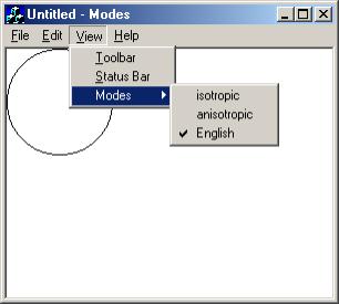
Add a pop-up menu to the [View] menu called [Modes]. [Modes] contains three items that allow the user to dynamically change the mapping mode between MM_HIENGLISH, MM_ISOTROPIC, and MM_ANISOTROPIC.
After setting the mapping mode, but before drawing the circle, OnDraw() must set the window and view port extents:
CRect client;
GetClientRect(&client);
pDC->SetWindowExt(1000, 1000);
pDC->SetViewportExt(client.right, -client.bottom);
The last two calls are ignored when the mapping mode is fixed (i.e., not a variable mapping mode).
Experiment with this program. What happens to the circle in each mapping mode as the view is resized?
If the view is resized so that it is 600 pixels wide and 400
pixels tall, and if a pixel is 1/1500 inches in diameter, then what point will
the rightmost point on the circle,
(500, -250) in logical coordinates, be mapped to in device coordinates assuming
the mapping mode is MM_ANISOTROPIC? MM_ISOTROPIC? MM_LOENGLISH?
Describe some applications where variable scale mapping modes might be used.
5.6.2 Problem: MyWord 2.0
Enhance MyWord 1.0 implemented in problem 4.11.2 by providing a menu called [Format]. The [Format] menu provides options that allow the user to change the typeface, size, and style of the text. (How could we allow users to change the typeface, size, and style of selected text within a document?)
Version 2.0 of MyWord is a WYSIWYG word processor. The printed text and the displayed text should exactly match.
Version 2.0 also provides scroll bars that allow the user to examine large documents. As the size of the document increases, the number of pages increases, too.
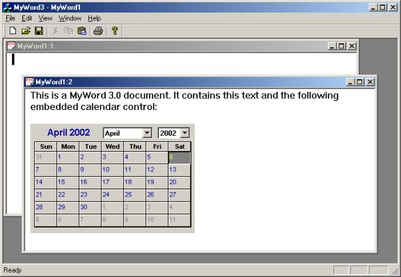
5.6.3 Problem: Rich Edit Views and MyWord 3.0
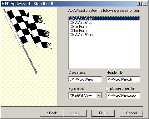
Use the MFC App Wizard to generate MyWord3, version 3.0 of the MyWord word processor. Accept all defaults except in the [Step 6 of 6] dialog, specify CEditView as the base class of CMyWord3View:
Click the [Finish] button. You will be prompted to add OLE container support:
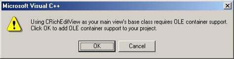
OLE stands for Object Embedding and Linking: the ability to include and view objects from other applications into MyWord documents. Click the [OK] button. Test and build the application.
Which features work in version 3.0? Which features are absent?
Enhance version 3.0 by allowing multiple views of a document. Under the [Edit] menu add an item that allows users to change the font of the selected text. (Hint: Use the GetRichEditCtrl() function to get the associated CRichEditCntrl object. This provides a number of useful formatting operations.
5.6.4 Problem: Draw 2.x
Complete and test version 2.0 of the Draw program.
5.6.4.1 Problem: Draw 2.1 with custom Shape-Dependent Dialogs
Modify Draw 2.0 so that clicking on different types of shapes (including future shapes) can bring up different types of dialogs. Use this feature to provide a custom dialog box for labels that allows users to change the text of the label.
5.6.4.2 Problem: Draw 2.2 with Polygons
Add a new Shape-derived class called Polygon to the Draw program. A polygon is centered in its bounding box. The diameter of a polygon is half the minimum of the width or the height of its bounding box. The number of sizes a polygon has is a variable ranging between 3 and 20.
5.6.4.3 Problem: Draw 2.3 with Line Segments
Add a new Shape-derived class called Segment to the Draw program. A segment is a line segment that connects the bottom left corner of its bounding box to the top right corner, if it has positive slope. If it has negative slope, then it connects the top left corner to the bottom-right corner. How could vertical and horizontal line segments be implemented?
5.6.4.4 Problem: Draw 2.4 with a Group/Ungroup Mechanism
Add two new member functions to the Composite class called Group() and UnGroup():
class Composite: public Shape
{
ShapeList members;
public:
void Group(ShapeList group);
void UnGroup(Composite* composite);
// etc.
};
The Group() function removes every shape in group from the model's members list, creates a composite shape from group, then adds the composite shape back into the model's members list. In other words, the Group() function replaces several model members by a composite shape.
The UnGroup() function removes its argument— a composite shape created by calling Group()— from the model's members list, then appends the members of its argument to the model's member list. In other words, UnGroup() is the inverse of Group().
Where will the Group() function get its argument from? For this we need to replace the model's current shape by a current shapes list. Normally, this list contains only a single item, the selected shape, but when a user performs a group select, then the list contains multiple shapes. Typically, group selection is done by holding down the [Shift] key while clicking on shapes with the mouse. We can test if the [Shift] key is down in the left mouse button handler by using the MK_SHIFT mask:
void CDraw2View::OnLButtonDown(UINT nFlags, CPoint point)
{
CDraw2Doc* pDoc = GetDocument();
if (nFlags & MK_SHIFT)
{
// add selected shape to
currentShapes list:
pDoc->Select(point);
}
else
{
pDoc->RemoveAll(); // empty currentShapes list
pDoc->Select(point);
}
CView::OnLButtonDown(nFlags, point);
}
Add two new items to the [Shapes] menu: [Group] and [Ungroup]. Selecting [Group] calls the model's Group() function, passing it the currentShapes list as an argument. Selecting [Ungroup] calls the model's Ungroup() function, passing it the head of the currentShapes list as an argument.
For this exercise you will need to implement the Composite::Move() function so that it moves every member by an appropriate offset.
5.7 Problem: Graph 1.0
This problem is a substantial project that introduces several advanced concepts. Although some of the code is given, there are big gaps and readers will need to figure out how to organize the code.
A graphing calculator plots the graphs of equations of linear, quadratic, cubic, trigonometric, and exponential functions specified by the user:
A [Graph] menu allows users to display dialog boxes that allow the user to specify the coefficients for each type of function. For example, the [Quadratic] dialog allows the user to specify the coefficients of the x2, x, and constant terms:
(Of course we really only need the [Cubic] dialog since quadratic and linear functions are just special cases of the cubic.) The [Trig] dialog allows the user to set the amplitude, shift, phase, and frequency of sine and cosine functions:
The [Graph] menu also has a [Set World] item that allows the user to specify the center, height, and width of a rectangular region of the Cartesian plane where the function is to be plotted:
5.7.1 Designing the Graphing Program
A Graph document encapsulates a function to be graphed, a "world" box (i.e., rectangular region of the real plane), and the segment of the graph that lies within the world box. A graph is simply a dynamic array of points of the form (x, f(x)), where f is a function. The Graphing calculator represents functions as objects called functors.
Each time the user modifies the world box or the function, the document's Plot() function is called to update the graph and notify all subscribing views.
Views also contain a box, a graph, and a Plot() function, only the box represents the client region of the view, not the world. The Plot() function is called by OnUpdate(). It creates a distortion-free transformation that maps points in the document's world box into points in the view's view box. The transformation is then applied to the points in the document's graph to produce the view's graph, and the window is invalidated. This triggers a call to the view's OnDraw() function, which uses the device context's Polyline function to draw the graph.
5.7.2 Implementing the Graphing Program (Hints)
5.7.2.1 Functors
The 1980's saw several challenges to the traditional imperative programming paradigm. The two most successful were the functional paradigm and the object-oriented paradigm. At the risk of over simplification, we may say that both of these schools objected to the sharp distinction imperative programs made between control (i.e., functions) and data. Thanks to polymorphism, objects— the data of an object oriented program— also determine the flow of control through the program, while the functions of a functional program can also serve as the program's data.
Although when described this way, the functional and object-oriented paradigms sound like polar opposites, the dividing line between them can be hazy. For example, like other forms of data, objects can be represented by functions in functional programs, while functions can be represented by objects in object-oriented programs.
Objects that represent functions are called function objects or functors. Functors are useful when functions are literally the data of a program. This is the case with the graphing calculator, which must dynamically create and plot functions. In C++ a functor is simply an object that overloads the function call operator, hence can be called like an ordinary function. If f is a functor, then the statement:
f(x, y, z);
translates into:
f.operator()(x, y, z);
Which can be defined by the programmer to compute the value of the function represented by f.
Step:
i. Use the [Insert]/[New Class ...] menu to create a new, generic class called Functor.
ii. Overload the function call operator as a virtual function.
iii. Provide a virtual function that returns the formula for the function as a string.
iv. Use a typedef to define Real to be double near the top of Functor.h.
v. Include <cmath>[3] near the top of Functor.h.
Although functors can represent functions with any domain and range, we will restrict ourselves to functors with domain and range equal to the real numbers. For the sake of abstraction, we define a real number to be a double:
typedef double Real;
Although declared virtual, we provide a default implementation of the function call operator as the identity function.
class Functor
{
public:
virtual Real operator()(Real x) {
return x; }
virtual CString ToString()
{
CString fun;
fun.Format("x");
return fun;
}
};
5.7.2.2 Real Points, Graphs, and Boxes
The graph of a function, f, is the set of all points in the real plane of the form (x, f(x)). We can approximate this in MFC as a CList or CArray of sample points:
typedef CArray<RPoint, RPoint> RGraph;
Points in the real plane are approximated by instances of the RPoint class, which is analogous to MFC's CPoint class, except coordinates are real numbers instead of integers.
Let RBox be the class of all rectangles in the real plane. RBox is analogous to CRect except the height and width are real numbers and the center is an RPoint.
5.7.2.3 Transforming the World onto a Canvas
Earlier, we made a distinction between the canvas and the view. Both are rectangles, but the canvas is an abstraction of a printed page or document. We may choose to measure distances on a canvas in terms of millimeters or inches, the canvas size can be fixed or determined by the document size, and we are free to define coordinate systems on a canvas in any way we choose. By contrast, view distances are measured in screen pixels, view coordinates are device coordinates, and the size of a view is determined by the user. By decoupling the canvas from the view we are free to define the layout and formatting of our graphics in advance. Displaying the canvas in a particular view is just a matter of a mathematical transformation of one rectangle onto another. (These transformations are CDC member functions.)
Of course neither the view nor the canvas are necessarily the same as the actual region of the real plane containing the part of a graph we are interested in. Distances in this region might be measured in miles, light years, or more abstract units such as dollars, kilograms, or seconds. To describe this region we will need a third rectangle (i.e., an RBox) called the world. By decoupling the world from the canvas, we can describe a graph in terms of its own units. Displaying the world on a canvas is just a matter of another mathematical transformation of one rectangle onto another:
Clearly, the ability to transform one rectangle onto another without distortions is an important technique in graphics programming. Fortunately, these techniques have been highly developed and refined by mathematicians, and are the subject of standard undergraduate texts and courses in Linear Algebra.
Geometrically, any rectangle, A, can be transformed into any other rectangle, B, in four steps. In step 1, A is moved so that its center coincides with the origin of the real plane. This is called a translation:
In step 2, A is compressed or stretched so that is the same size as B. This is called scaling:
In step 3, A is twisted so that its orientation matches the orientation of B. This is called rotation:
Finally, A is translated again so that its center coincides with B's center:
(p + q).x = p.x + q.x
(p + q).y = p.y + q.y
If q is the result of scaling p, then the x and y coordinates of q are multiples of the x and y coordinates of p:
q.x = a * p.x
q.y = b * p.y
where a and b are called scaling factors. We can express this as matrix multiplication:
q = S * p
where:
S00 = a
S11 = b
S10 = S01 = 0.
If q is the result of rotating p counter-clockwise through an angle of x radians, then we can express the x and y coordinates of q as a linear combination of the x and y coordinates of p:
q.x = cos(x) * p.x – sin(x) * p.y
q.y = sin(x) * p.x + cos(x) * p.y
We can express this as matrix multiplication, too:
q = R * p
where:
R00 = R11 = cos(x)
R01 = -sin(x)
R10 = sin(x)
If q is the result of first scaling, then rotating p, then we can express this as the matrix equation:
q = M * p
where M = R * S.
We can now describe the transformation of any point p in rectangle A into a point q in rectangle B by the matrix equation:
q = T(p) = M(p - Acp) + Bcp
S00 = B.Width/A.Width
S11 = B.Height/A.Width
S10 = S01 = 0
and R is a standard rotational matrix. Usually, the angle of rotation will be 0, which will make B the identity matrix, in which case M will be the same as S.
5.7.2.4 Implementing Transformations
Given the usefulness of transformations, it will be handy to have a reusable implementation.
Step:
i. Use the [Insert]/[New Class ...] menu to create a new, generic class called Transformation.
ii. Use the [Change] button to name the header file trans.h and the implementation file trans.cpp.
iii. Add the definitions of Real, RPoint, RBox, and RGraph to the beginning of trans.h
Be sure to add the following include directives to the top of trans.h:
#include <afxtempl.h>
#include <cmath>
Assume T is a transformation[4] given by the matrix equation:
T(p) = M * (p - r) + s
(where M is the 2 x 2 rotate-and-scale matrix, and r and s are the translation vectors.) Recall from Linear Algebra that the determinant of M is given by the equation:
|M| = M00M11 – M01M10
M-100 =
M11/|M|
M-101 = -M01/|M|
M-110 = -M10/|M|
M-111 = M00/|M|
If M-1 exists, then T-1, the inverse of transformation T, is given by:
T-1(p) = M-1 * (p – s) + r
We will represent T as an object. More specifically, as a functor with domain and range equal to RPoint. As an object, T encapsulates M and M-1 (as 2 x 2 arrays of Reals), u and v (as RPoints), and |M|. Here's a partial declaration of our Transformation class:
class Transformation
{
public:
// = mat * (p + translation1) +
translation2:
RPoint operator()(const RPoint& p)
const;
// = inv * (p - translation2) -
translation1:
RPoint inverse(const RPoint& p)
const;
// compute mat, determinant, and
inv:
void UpdateMatrix();
// etc.
protected:
RPoint scale;
RPoint translation1, translation2;
Real rotation; // counter-clockwise
radians
Real determinant; // = |mat|
bool invertible; // = (determinant != 0)
Real mat[2][2]; // = rotate & scale matrix
Real inv[2][2]; // = inverse of mat
};
The 2 x 2 array of Reals, mat, represents the scale-and-rotate matrix of the transformation, M; the Real member variable, determinant, is the determinant of mat, |M|, and, if it is non-zero, then inv represents the inverse of mat, M-1. The RPoint member variables, translation1 and translation2, represent the first and second translation vectors of the transformation (v and w, respectively). The x and y coordinates of the RPoint member variable, scale, represent the x and y scaling factors of the transformation, and the Real member variable, rotation, represents the counter-clockwise angle of rotation in radians of the transformation.
Although not shown, the Transformation class provides getter and setter functions that allow the user to inspect and modify the translations, rotation angle, and scaling factors of a transformation. Of course if these numbers are modified, then mat, determinant, and inv must be updated. For example:
void Transformation::SetRotation(Real theta)
{
rotation = theta;
UpdateMatrix();
}
The UpdateMatrix() function uses the formulas described earlier to re-compute mat, inv, and determinant:
void Transformation::UpdateMatrix()
{
Real cosine = cos(rotation);
Real sine = sin(rotation);
mat[0][0] = scale.x * cosine;
mat[0][1] = -scale.y * sine;
mat[1][0] = scale.x * sine;
mat[1][1] = scale.y * cosine;
determinant = mat[0][0] * mat[1][1] -
mat[0][1] * mat[1][0];
invertible = (DELTA <
abs(determinant));
if (invertible)
{
inv[0][0] = mat[1][1]/determinant;
inv[0][1] = -mat[0][1]/determinant;
inv[1][0] = -mat[1][0]/determinant;
inv[1][1] = mat[0][0]/determinant;
}
}
In general, its a bad idea to compare double precision numbers using literal equality. Rounding errors creep into calculations and accumulate so that two numbers that should be identical end up differing by some small amount. For this reason we judge a matrix to be non-invertible when its determinant is near zero:
invertible = (DELTA < abs(determinant));
where DELTA is defined at the top of trans.h:
#define DELTA 1e-10
5.7.2.4.1 Applying a Transformation to a Point
Transformations are functors. In other words, the Transformation class overloads the function call operator, so we can apply transformations to points using function call syntax:
RPoint p, q;
Transformation T;
q = T(p); // same as q = T.operator()(p);
The implementation of the overloaded function call operator is based on the general equation for a transformation given earlier:
RPoint Transformation::operator()(const RPoint& p) const
{
Real xc = mat[0][0] * (p.x +
translation1.x) +
mat[0][1] * (p.y + translation1.y) +
translation2.x;
Real yc = mat[1][0] * (p.x +
translation1.x) +
mat[1][1] * (p.y + translation1.y) +
translation2.y;
return RPoint(xc, yc);
}
The implementation of the inverse() function, which computes the inverse of the transformation, is left as an exercise, as well as the implementation of a constructor that initializes member variables in some reasonable way.
5.7.2.4.2 Box-to-Box Transformations
Our main application of transformations will be to transform worlds into canvases. For this type of problem it will be convenient to have a way to create a transformation from a pair of RBoxes representing the world and the canvas. We could have introduced an additional constructor into the Transformation class for this purpose, but this might confuse future clients of the class who aren't interested in RBoxes. Instead, we will add the necessary constructors to a class derived from the Transformation class.
Here's the declaration of BoxToBox:
class BoxToBox: public Transformation
{
public:
BoxToBox(const RBox& fb, const
RBox& tb)
{
SetBoxes(fb, tb);
}
void SetBoxes(const RBox& fb, const
RBox& tb);
// etc.
private:
RBox fromBox; // the world
RBox toBox; // the canvas
};
The constructor simply passes its parameters to the SetBoxes() function, which uses the sizes of the boxes to initialize the scaling factors, and their centers to initialize the translation vectors:
void BoxToBox::SetBoxes(const RBox& fb, const RBox& tb)
{
fromBox = fb;
toBox = tb;
rotation = 0;
scale.x = toBox.width/fromBox.width;
scale.y = toBox.height/fromBox.height;
translation1.x = -fromBox.center.x;
translation1.y = -fromBox.center.y;
translation2 = toBox.center;
UpdateMatrix();
}