1. Object-Oriented Design
Object-Oriented Development
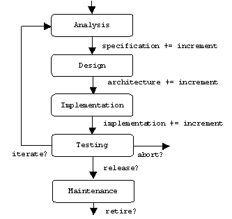
A software project usually involves three participants: the client commissions the software, the developer builds the software, and the user uses the software. These roles may be played by individuals or organizations. In fact, all three roles may be played by the same actor, but it will still be important for the actor to remember which role he is playing at any given moment. Just as a play is divided into carefully scripted acts and scenes, a software project follows a carefully scripted development process, which is usually divided into five phases:
Analysis
: All three participants create a specification document that describes the application's requirements as well as the application domain's important terms, concepts, and relationships.Design: Using the specification document as a guide, the developer creates an architectural document that describes the application's important classes, together with their responsibilities and collaborations.
Implementation: Using the architectural document as a guide, the developer implements the classes it describes. The developer may need to introduce supporting classes.
Testing: Of course the developer tests the structure and function of each class he implements (unit testing), but the application must also be tested as a whole, first by the developer (integration testing), then by the users (acceptance testing). Integration testing is the riskiest phase.
Maintenance: Maintenance involves fixing bugs (corrective maintenance), porting the application to new platforms (adaptive maintenance), and adding new features (perfective maintenance). Maintenance is the longest and costliest phase.
Iterative-incremental development processes mitigate the risk of integration testing by allowing the developer to iterate through these phases many times. Each iteration produces an increment of the specification document, architectural document, and a tested implementation. Typically, high priority and high risk requirements are attacked during the early iterations. Thus, a decision to abort a project can be made early, before too much money has been spent:

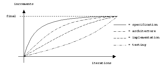
In theory, a developer may be working on the specification near the end of the project and the implementation near the beginning. In practice, most of the specification is completed during the early iterations through the specification phase. Only finishing touches might be added late in the project. Administrative issues such as resolving file dependencies and implementing constructors and destructors are typical activities during the early iterations through the implementation phase, while implementing low-level supporting functions is more common during the late iterations. The following graph gives a rough idea of the maturity rates of the specification, architecture, implementation, and test plan as time passes:
Design Overview
The input to the design phase, the specification document, can be understood as a description of the behavior of the system to be built. By behavior, we of course mean externally observable behavior, the input-output behavior. Input-output behavior is implicitly or explicitly understood as a collection of functions that realize system requirements. A function might be described in a specification document as one or more use cases:
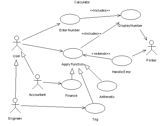
The output of the design phase, the architectural document, is also a specification; it specifies the internal structure of the system, and therefore serves as a roadmap for the programmers who will implement the system. Design is use-case driven. Every element in the architectural document must trace back to a use case that it supports.
The main processes that occur in the design phase are decomposition and abstraction. The system is decomposed into modules. These modules are decomposed into sub-modules, and so on. Each module is an abstraction: the description of its purpose or behavior is independent of its implementation.
What is a module? To some degree the answer to this question depends on the design phase iteration. During the early iterations, module might mean subsystem. During late iterations, module might mean function or data structure. During the intense middle iterations, the definition of module depends on the design strategy.
Functional strategies decompose systems into hierarchies of functions and their supporting functions, with system state maintained by a centralized global data structure:
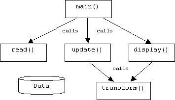
Wirth's Structured Programming is the simplest example of a functional strategy. It combines top-down decomposition with stepwise refinement. Other examples include:
Structured Design (Constantine and Yourdon)
Jackson Structured Programming (Jackson)
Wainer-Orr (Wainer)
Object-oriented strategies are data-driven. Instead of a centralized repository, system state is distributed among objects that encapsulate some part of the system state. These objects drive the application by passing messages to each other to request some modification of the system state. Naturally, an object is only authorized to modify the portion of the system state that it encapsulates.
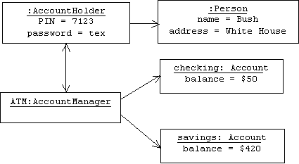
Examples of object-oriented design strategies include:
OMT (Rumbaugh)
Booch Method (Booch)
The Unified Process (Booch, Rumbaugh, and Jacobson)
The focus of these notes will be object-oriented design. Although the development process described earlier is based on the Unified Process, our approach to design will be pattern-oriented. We will build designs by combining design patterns-- reusable groups of reusable classes and objects that collaborate with each other in canonical ways.
Extreme Programming
The goal of design is to make the inevitable system modifications less traumatic. A good design is easy to modify. That is the accepted wisdom. A few developers are beginning to challenge this view. Extreme Programming or X Programming is based on refactoring. Refactoring is a collection of techniques for repairing defective designs (also called anti-patterns). Accepting that all designs are inherently defective, X Programmers only devote enough time to the design phase to produce a design that supports the current set of requirements. Later, when more requirements are added to the specification, refactoring techniques are used to extend the design to the new requirements. A carefully designed suite of regression tests ensures that the modified design still supports the original requirements.
UML
The Universal Modeling Language (UML) is a family of diagram types that appear prominently in specification and architectural documents. UML was developed by Rational Software corporation [WWW-6] and was subsequently chosen by OMG, the Object Management Group [WWW-14], as the "industry standard" object-oriented modeling language. As such, UML replaces or incorporates several competing languages that preceded it.
Although UML describes many types of diagrams, we will only use a restricted subsets of class, package, object, and interaction (sequence) diagrams. For a description of UML, the reader should consult [FOW-1] or any of the dozens of other books that are currently available.
Design Quality
The goal of every program is to be useful (solve the right problems), usable (easy to use), and modifiable (easy to maintain). Two important design principles that help developers achieve the last goal are modularity and abstraction:
The Modularity Principle
Systems should be decomposed into cohesive, loosely coupled modules (classes or functions).
The Abstraction Principle
The interface of a module (class or function) should be independent of its implementation.
A cohesive class has a unified purpose, while loose coupling implies dependencies on other classes are minimal. Taken together, this makes a class easier to reuse, replace, and understand. The abstraction principle implies that the clients of class A (now defined as classes that depend on A) don't need to understand the implementation of A in order to use it. Conversely, the implementer of A is free to change implementation details without worrying about breaking the client's code.
Cohesion
The member functions of a cohesive class work together to achieve a common goal. Classes that try to do too many marginally related tasks are difficult to understand, reuse, and maintain.
Although there is no precise way to measure the cohesiveness of a class, we can identify several common "degrees" of cohesiveness. At the low end of our spectrum is coincidental cohesion. A class exhibits coincidental cohesion if the tasks its member functions perform are totally unrelated:
class MyFuns {
void initPrinter() { ... }
double calcInterest() { ... }
Date getDate() { ... }
}
The next step up from coincidental cohesion is logical cohesion. A class exhibits logical cohesion if the tasks its member functions perform are conceptually related. For example, the member functions of the following class are related by the mathematical concept of area:
class AreaFuns {
double circleArea() { ... }
double rectangleArea() { ... }
double triangleArea() { ... }
}
A logically cohesive class also exhibits temporal cohesion if the tasks its member functions perform are invoked at or near the same time. For example, the member functions of the following class are related by the device initialization concept, and they are all invoked at system boot time:
class InitFuns {
void initDisk() { ... }
void initPrinter() { ... }
void initMonitor() { ... }
}
One reason why coincidental, logical, and temporal cohesion are at the low end of our cohesion scale is because instances of such classes are unrelated to objects in the application domain. For example, suppose x and y are instances of the InitFuns class:
InitFuns x = InitFuns(), y = new InitFuns();
How can we interpret x, and y? What do they represent? How are they different?
A class exhibits procedural cohesion, the next step up in our cohesion scale, if the tasks its member functions perform are steps in the same application domain process. For example, if the application domain is a kitchen, then cake making is an important application domain process. Each cake we bake is the product of an instance of a MakeCake class:
class MakeCake {
void addIngredients() { ... }
void mix() { ... }
void bake() { ... }
}
A class exhibits informational cohesion if the tasks its member functions perform are services performed by application domain objects. Our Airplane class exhibits informational cohesion, because different instances represent different airplanes:
class Airplane {
void takeoff() { ... }
void fly() { ... }
void land() { ... }
}
Note that the informational cohesion of this class is ruined if we add a member function for computing taxes or browsing web pages.
Coupling
An association from class A to class B implies a dependency of A on B. Changes to B could force changes to A. The question is, what type of changes to B are likely to force changes in A? If A and B are loosely coupled, only major changes to certain member functions of B should impact A. If A and B are tightly coupled, then small changes to B can have a dramatic impact on A.
Although there is no precise way to measure how tightly an association couples one class to another, we can identify several common coupling "degrees". For example, assume an E-commerce server keeps track of customers and the transactions they commit:

Normally, this would mean that the Transaction class has a member variable that points to a Customer:
class Transaction {
Customer customer;
// etc.
}
Some changes to the Customer class will impact the Transaction class, but some will not. For example, changing the private members of the Customer class should have no impact. This is the most common form of coupling. For lack of a better term, we will call this client coupling.
On the other hand, if a C++ Transaction class is a friend of the Customer class:
class Customer
{
friend class Transaction;
// etc.
};
Then Transaction is content coupled to Customer. Changes to the private members of Customer could impact Transaction. Declaring one class to be the friend of another tightens the coupling between the two classes.
If Customer is an interface for corporate and individual customers:

Then the Transaction class can't even be sure what type of object its customer pointer points at. There is no mention in the Transaction class of corporate or individual customers, only customers. Transactions can call public Corporate and Individual member functions that are explicitly declared in the Customer interface. Other public member functions such as Corporate::getCEO() or Individual::getSpouse() are not visible to transaction objects. Transaction exhibits interface coupling with the Corporate and Individual classes. Obviously interface coupling is looser than client coupling.
Message passing also helps to loosen the coupling between objects. For example, suppose an object representing an ATM machine mediates between transactions and customers:
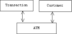
In this case transactions and customers communicate by passing messages through the ATM machine, which means that the transaction doesn't even need to know the location of the customer. We shall call this message coupling. Short of totally uncoupled, we can achieve the loosest form of coupling by combining interface and message coupling.